
Valve system for overhead-camshaft-type internal combustion engine, and engine incorporating same

a technology of camshaft and valve system, which is applied in the direction of valve drives, machines/engines, mechanical equipment, etc., can solve the problems of cam holder deformation, cam holder likely deformation, and difficult to realize the reduction of cam holder weight, so as to increase the wall thickness, enhance durability, and high structural rigidity

Inactive Publication Date: 2009-04-23
HONDA MOTOR CO LTD
View PDF2 Cites 19 Cited by
  • Summary
  • Abstract
  • Description
  • Claims
  • Application Information

AI Technical Summary

Benefits of technology

The present invention provides a valve system for an overhead-camshaft-type internal combustion engine. The cam holder is fastened to a cylinder head and includes a bottom wall and a pair of support walls with lower sides joined by the bottom wall. A rib joins the upper side portions of the support walls. The cam holder also includes rocker bearing portions that pivotally move rocker arms. The rib is integrally formed with the cam holder or separately formed and fastened together with the cam holder using a fastening member. The cam holder has a side wall that joins the support walls on a side opposite to where the rocker bearing portions are formed. The technical effects of the invention include improved stability and reduced noise in the valve system.

Problems solved by technology

Hence, the cam holder is likely to be deformed due to such repetition of widening or narrowing of the distance between the support walls.
In this case, however, it is difficult to realize the reduction of weight of the cam holder.
However, the deformation of the cam holder attributed to the repetitious widening or narrowing of the distance between the support walls is easily generated between front side portions of the cam holder.
In order to prevent (or minimize) the generation of the deformation attributed to widening or narrowing the distance between the support walls, it is necessary to ensure the rigidity by increasing a thickness of the portion of the cam holder which is influenced by a stress and hence, it is more difficult to realize the reduction of weight of the cam holder.

Method used


Image

  • Valve system for overhead-camshaft-type internal combustion engine, and engine incorporating same
  • Valve system for overhead-camshaft-type internal combustion engine, and engine incorporating same
  • Valve system for overhead-camshaft-type internal combustion engine, and engine incorporating same

Examples


Embodiment Construction

[0035]It should be understood that only structures considered necessary for illustrating selected embodiments of the present invention are described herein. Other conventional structures, and those of ancillary and auxiliary components of the system, will be known and understood by those skilled in the art.

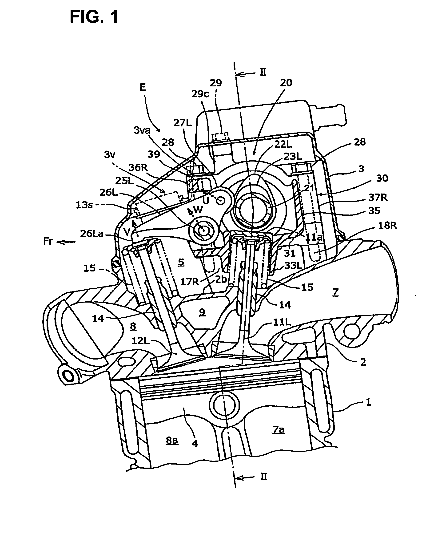
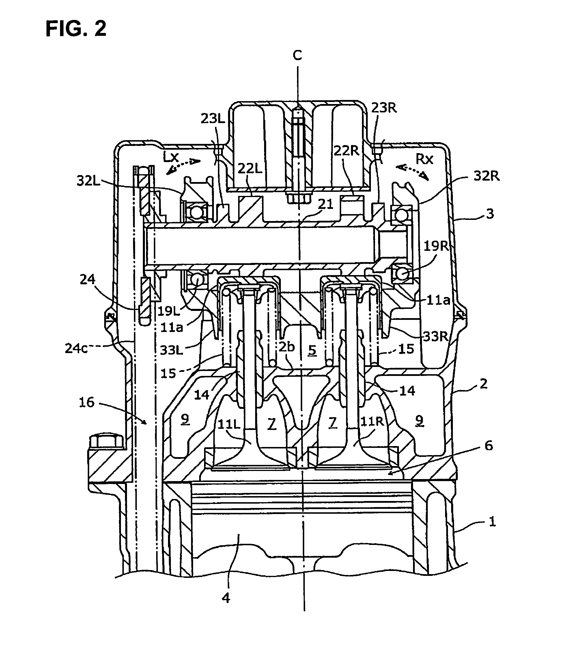
[0036]Hereinafter, one embodiment according to the invention is explained in conjunction with FIG. 1 to FIG. 8.

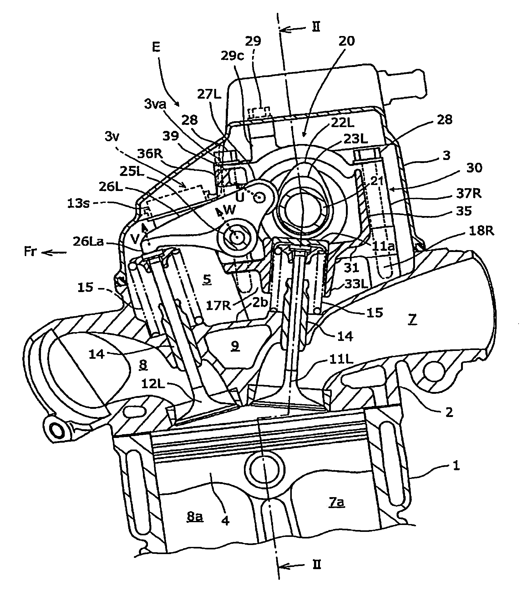
[0037]An internal combustion engine E of this embodiment is a water-cooled overhead-camshaft-type 4-cycle internal combustion engine which is mounted on a motorcycle in a state that a crankshaft of the engine is directed in a vehicle width direction. In the internal combustion engine E, a cylinder 1 and a cylinder head 2 extend in the substantially upward direction from a crankcase in a state that the cylinder 1 and the cylinder head 2 overlap with each other, and a cylinder head cover 3 is mounted on the cylinder head 2. The cylinder head cover covers a valve system 20 m...


PUM


Abstract

A valve system of an overhead-camshaft-type internal combustion engine includes a cam holder fastened to a cylinder head having a combustion chamber formed therein. The cam holder supports a camshaft, and is disposed above the combustion chamber. The cam holder includes a bottom wall, a pair of oppositely-facing support walls having lower sides thereof joined with each other by the bottom wall, and a rib joining predetermined oppositely-facing portions of respective upper side portions of the support walls with each other. The support walls of the cam holder pivotally support the cam shaft. The rib may be integrated with the cam holder, or may be separately formed and fastened to the support walls of the cam holder.

Description

CROSS-REFERENCE TO RELATED APPLICATIONS[0001]The present application claims priority under 35 USC §119 based on Japanese patent application No. 2007-272511, filed on Oct. 19, 2007. The entire subject matter of this priority document is incorporated by reference herein.BACKGROUND OF THE INVENTION[0002]1. Field of the Invention[0003]The present invention relates to a valve system of an overhead-camshaft-type internal combustion engine, and an engine incorporating same. More particularly, the present invention relates to a reinforced cam holder which pivotally supports a camshaft of the valve system.[0004]2. Description of the Background Art[0005]There is a known valve system of an overhead cam-shaft-type internal combustion engine in which a cam holder, which pivotally supports a camshaft by both oppositely-facing support walls having lower sides thereof joined to each other by a bottom wall, is fastened to a cylinder head above a combustion chamber. An example of such valve system of...

Claims


Application Information

Patent Timeline
Patent Type & Authority Applications(United States)
IPC IPC(8): F01L1/02
CPCF01L1/022F01L1/053F01L1/181F02F7/006F01L2001/0535F01L2105/00F01L2001/0476F01L2305/00
Inventor OCHIAI, SHUICHIKURIBARA, HIROSHI
Owner HONDA MOTOR CO LTD
Learn More