Eureka AIR delivers breakthrough ideas for toughest innovation challenges, trusted by R&D personnel around the world.

Window cover and adjustable shade rail

a technology for window coverings and shade rails, which is applied in the direction of shutters/movable grilles, door/window protective devices, manufacturing tools, etc., can solve the problems of difficult storage of rails of different sizes, inconvenient storage, and inability to easily adjust the width of the rails by cutting, etc., to achieve convenient storage, reduce the amount of storage space, and reduce the effect of storage spa

Inactive Publication Date: 2009-04-23
TEH YOR CO LTD
View PDF6 Cites 6 Cited by
  • Summary
  • Abstract
  • Description
  • Claims
  • Application Information

AI Technical Summary

Benefits of technology

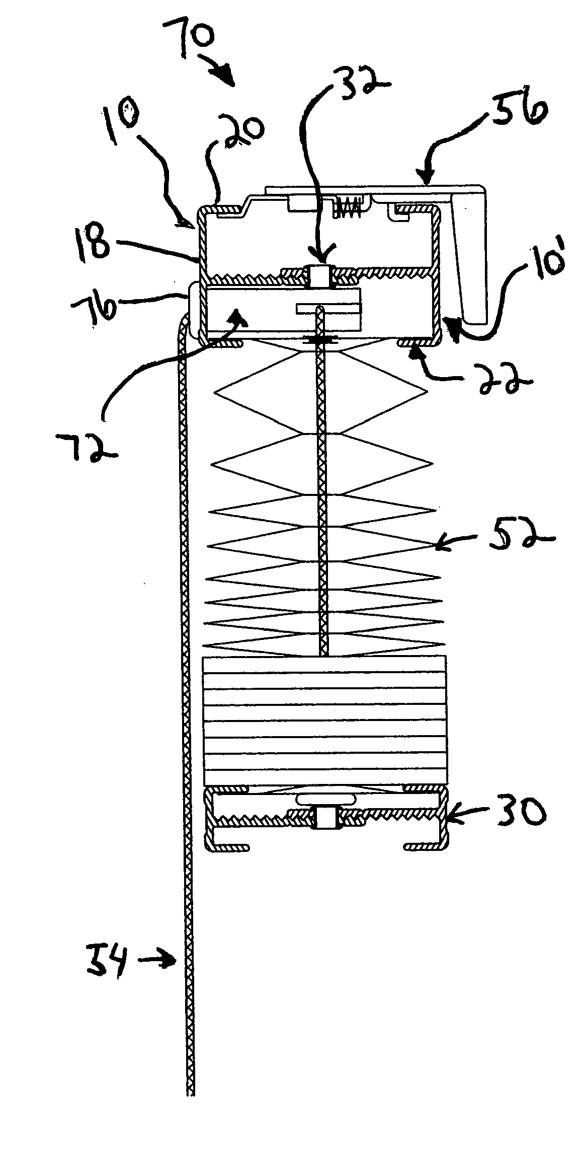
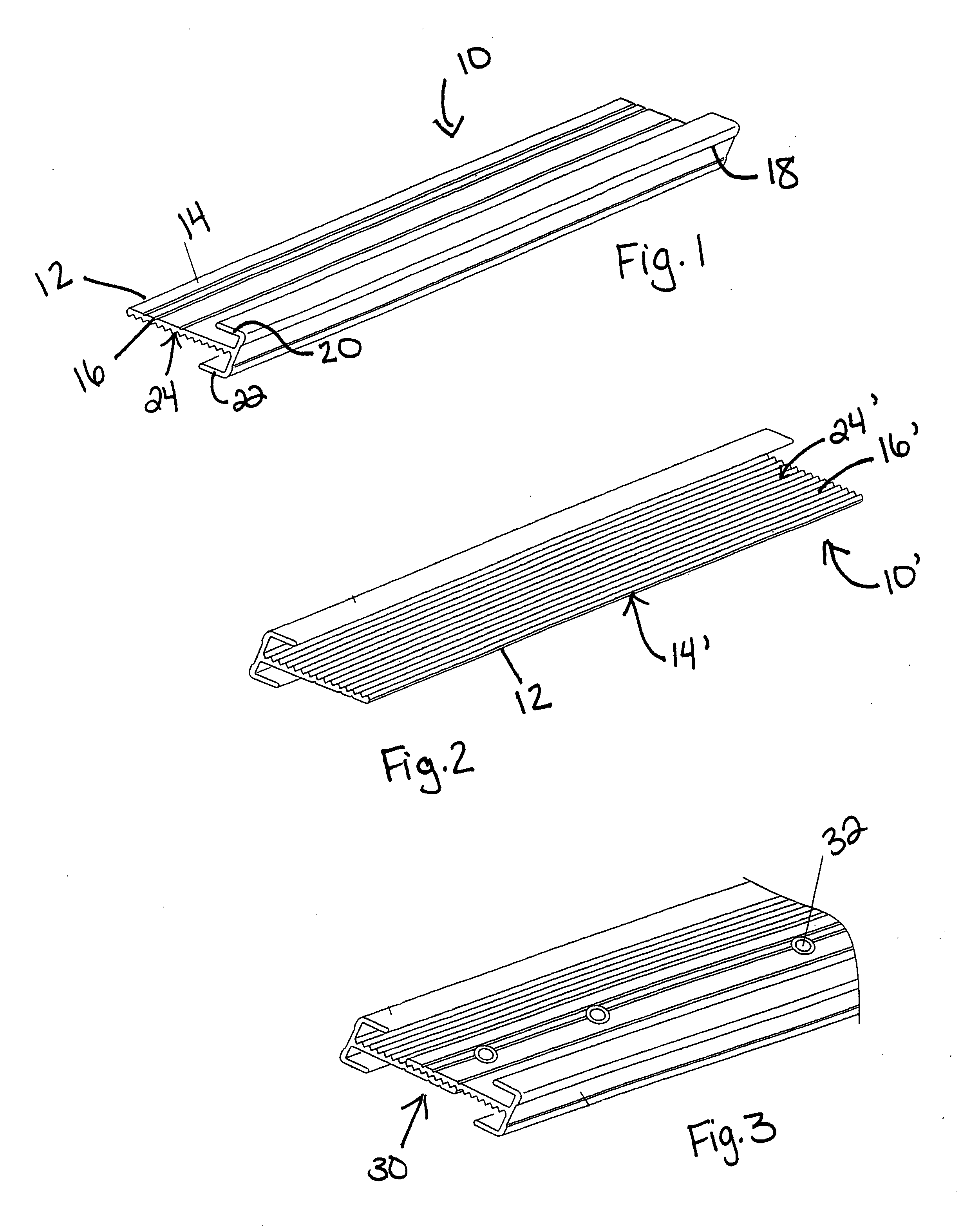
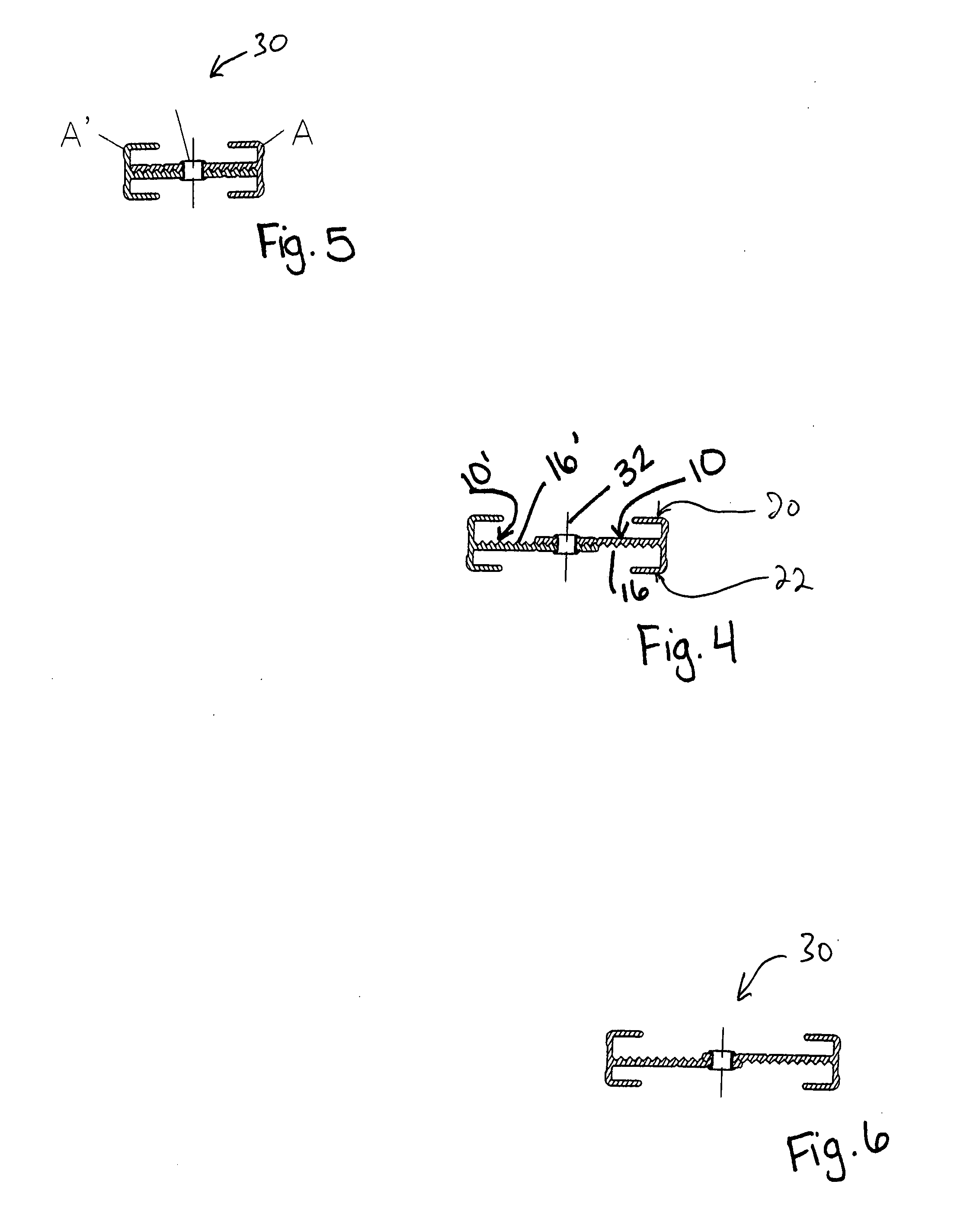
[0016]The base plate of a first rail element preferably is placed adjacent the base plate of a second rail element such that the bottom surface of one base plate is in overlapping contact with the top surface of the other base plate. In this configuration, the upright flange member of the first base plate is opposite the upright flange member of the second base plate. The two base plates preferably are connected with a connection member to form the adjustable shade rail. The width of the shade rail can be increased by reducing the amount of overlap between the base plates of the two rail elements. The width of the shade rail can be decreased by increasing the amount of overlap between the base plates of the two rail elements.
[0017]The base plates of the present invention may also include frictional engagement members on either its bottom surface or top surface or on both surfaces. These frictional engagement members preferably engage the complementary frictional engagement members on the overlapping second base plate in a manner that prevents slipping displacements between the two rail elements. The frictional engagement members can be formed in a variety of configurations. For example, the frictional engagement members can be a generally striated pattern containing grooves and teeth. The grooves and teeth can be of any shape and the distance between each tooth or groove can vary. The frictional engagement member can be of any other configuration that prevents the slipping displacement between the two rail elements.
[0020]The adjustable shade rail portion of the present invention reduces the amount of storage space previously required for the shade rails of the prior art. The rail elements of the present invention are easily stored because they can be combined with other identical or similar rail elements in the same storage space. The rail elements of the present invention also require little or no cataloging or other organizational indexing, because the rail elements are of the same or similar sizes and configurations.
[0021]Accordingly, the present invention provides an adjustable shade rail that requires a small amount of storage space and that can be customized to a desired width quickly and easily, and a window cover containing this adjustable shade rail.

Problems solved by technology

Unlike the length of the rail, which can be easily cut to fit the width of the window covering, the width of the rail cannot be easily adjusted by cutting.
A considerable amount of storage space is required to maintain an adequate stock of these differently-sized rails.
Rails of different sizes are difficult to efficiently store, because they cannot be stacked or combined with rails of different sizes.

Method used


Image

  • Window cover and adjustable shade rail
  • Window cover and adjustable shade rail
  • Window cover and adjustable shade rail

Examples


Embodiment Construction

[0033]The invention disclosed herein is susceptible to embodiment in many different forms. The embodiments shown in the drawings and described in detail below are only for illustrative purposes. The disclosures are intended as an exemplification of the principles and features of the invention, but do not limit the invention to the illustrated embodiments.

[0034]Referring to FIG. 1, a rail element 10 adapted for use with a window covering is shown. Rail element 10 includes a base plate 12 having a first surface 14 and a second surface 16. The base plate is preferably planar and generally flat. When not planar, the configuration should be chosen to allow two rail elements to be mounted together. Such a configuration can include matching curved surfaces which complement each other when stacked.

[0035]The base plate can also contain a staggered off-set portion created from a perpendicular turn along the surface of the base plate followed by another perpendicular turn that returns the base...


PUM

PropertyMeasurementUnit
lengthaaaaaaaaaa
dimensionaaaaaaaaaa
dimensionsaaaaaaaaaa

Abstract

An adjustable shade rail for use with a window covering and method of making the shade rail is provided by combining a first and second rail element. The width of the adjustable shade rail can be adjusted by varying the position of the first rail element in relation to the second rail element.

Description

FIELD OF INVENTION[0001]The present invention relates to a window covering or window shade containing a rail structure with adjustable dimensions that can be used as a head rail, bottom rail or intermediate rail of a window covering.BACKGROUND OF INVENTION[0002]Most commercially available window covering assemblies comprise a head rail located at the top of the window covering. The head rail supports a horizontal shaft that carries the cords or strings that support the window covering fabric or slats. Such a head rail is well known in the art, and one design of a head rail is shown in U.S. Pat. No. 4,531,563.[0003]Most commercially available window covering assemblies also comprise a bottom rail located at the bottom of the window covering. The bottom rail provides weight on the bottom of the window covering to keep the window covering relatively taut. Such a bottom rail is well known in the art, and is shown in various U.S. patents such as U.S. Pat. No. 5,927,366.[0004]Window cover...

Claims


Application Information

Patent Timeline
Patent Type & Authority Applications(United States)
IPC IPC(8): E06B9/24
CPCE06B9/262E06B9/388Y10T29/49826E06B2009/2627E06B2009/2441
Inventor YU, FU-LAIHUANG, CHIN-TIEN
Owner TEH YOR CO LTD
Why Eureka
Eureka Blog
Learn More