

Water Absorbing Materials Used as an In-flow Control Device
- Summary
- Abstract
- Description
- Claims
- Application Information
AI Technical Summary
Benefits of technology
Problems solved by technology
Method used
Image

Examples
Embodiment Construction
[0017]The present disclosure relates to devices and methods for controlling production of a hydrocarbon producing well. The present disclosure is susceptible to embodiments of different forms. There are shown in the drawings, and herein will be described in detail, specific embodiments of the present disclosure with the understanding that the present disclosure is to be considered an exemplification of the principles of the disclosure, and is not intended to limit the disclosure to that illustrated and described herein. Further, while embodiments may be described as having one or more features or a combination of two or more features, such a feature or a combination of features should not be construed as essential unless expressly stated as essential.
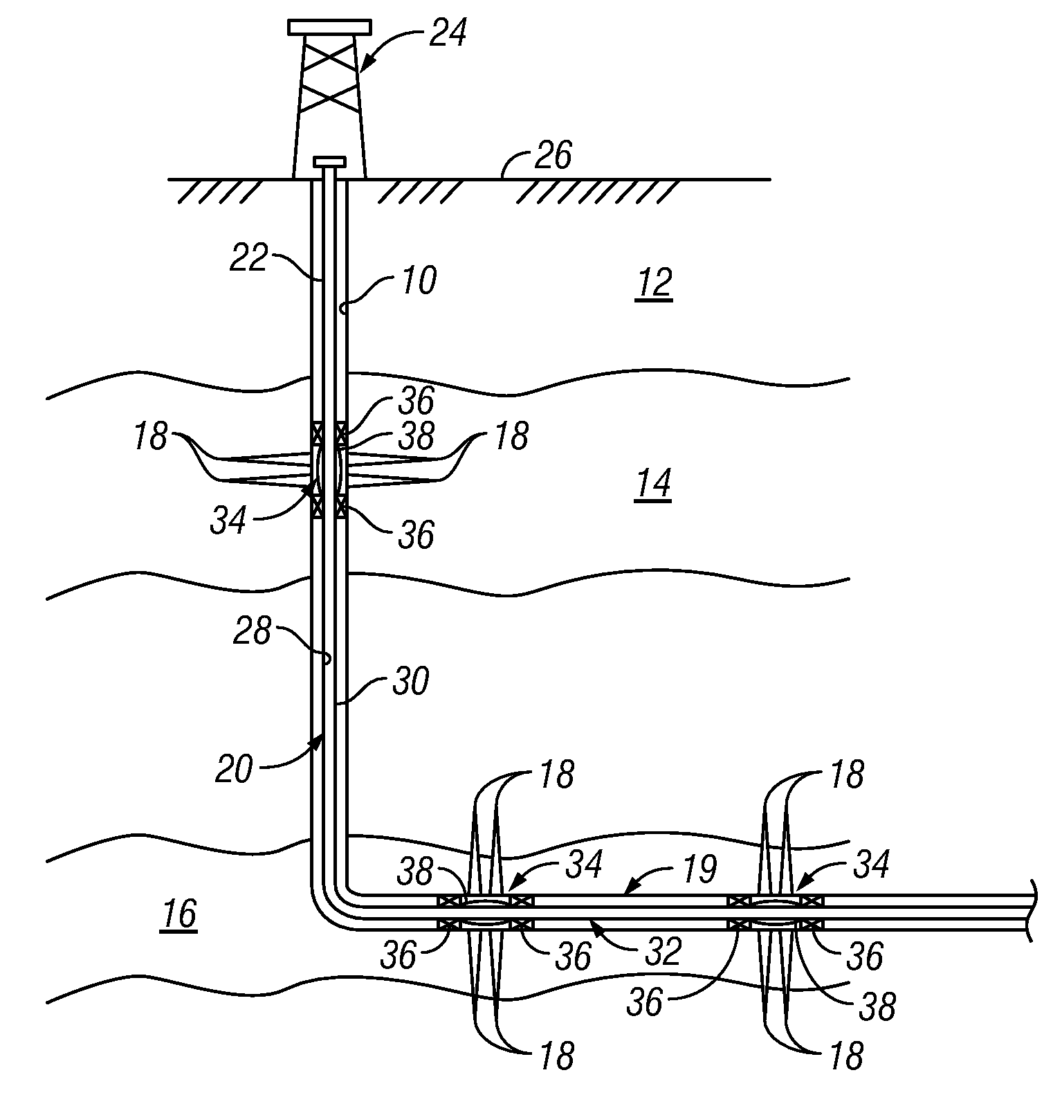
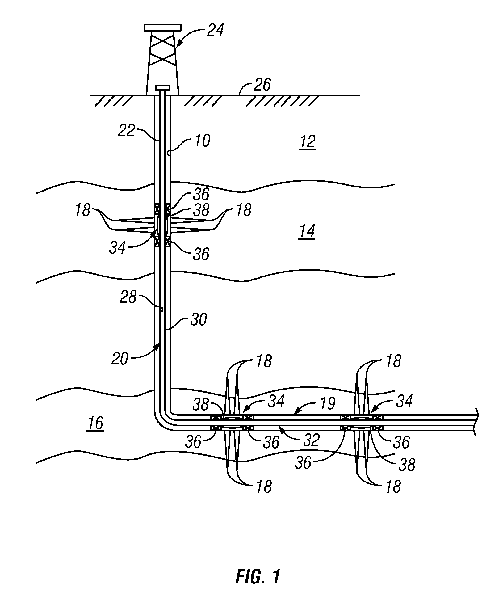
[0018]Referring initially to FIG. 1, there is shown an exemplary wellbore 10 that has been drilled through the earth 12 and into a pair of formations 14, 16 from which it is desired to produce hydrocarbons. The wellbore 10 is cased by m...
PUM
 Abstract
Description
Claims
Application Information