Microconcentrator/Microfilter

a technology of microconcentrator and filter, which is applied in the direction of membrane, separation process, multi-stage water/sewage treatment, etc., can solve the problems of limiting the place and time of separation, and large amount of capital equipment,

Inactive Publication Date: 2009-04-23
PRESIDENT & FELLOWS OF HARVARD COLLEGE
View PDF10 Cites 26 Cited by
  • Summary
  • Abstract
  • Description
  • Claims
  • Application Information

AI Technical Summary

Benefits of technology

[0011]In another embodiment, the present invention is directed to a method, comprising flowing a suspension comprising a fluid and at least a first component through a first microfluidic channel of a microfluidic filter, allowing a first portion of the fluid to pass through a second channel,

Problems solved by technology

These techniques typically require substantial capital equipment that can be both

Method used


Image

  • Microconcentrator/Microfilter
  • Microconcentrator/Microfilter
  • Microconcentrator/Microfilter

Examples


example 1

[0062]Example 1 demonstrates that a microfluidic filter can be fabricated using a one step soft-lithography method as described in U.S. Pat. No. 6,686,184. A brief description of this method is as follows. A chrome mask including a design of the microfilter channels was fabricated. A two micron high layer of SU-8 was spin coated onto a silicon wafer. The SU-8 was shined with UV light and developed. The wafer was recoated with a 25 micron layer of SU-8 and the channels of the filter were developed. Twenty-five grams of PDMS were poured over the silicon mold and degassed in a vacuum chamber. The inlet and the outlet holes were punched with a specially prepared twenty-gauge needle. The PDMS device was then sealed to a PDMS slab by oxidizing both pieces using an air plasma chamber. The inlet and the outlet holes were connected with PE-20 tubing.

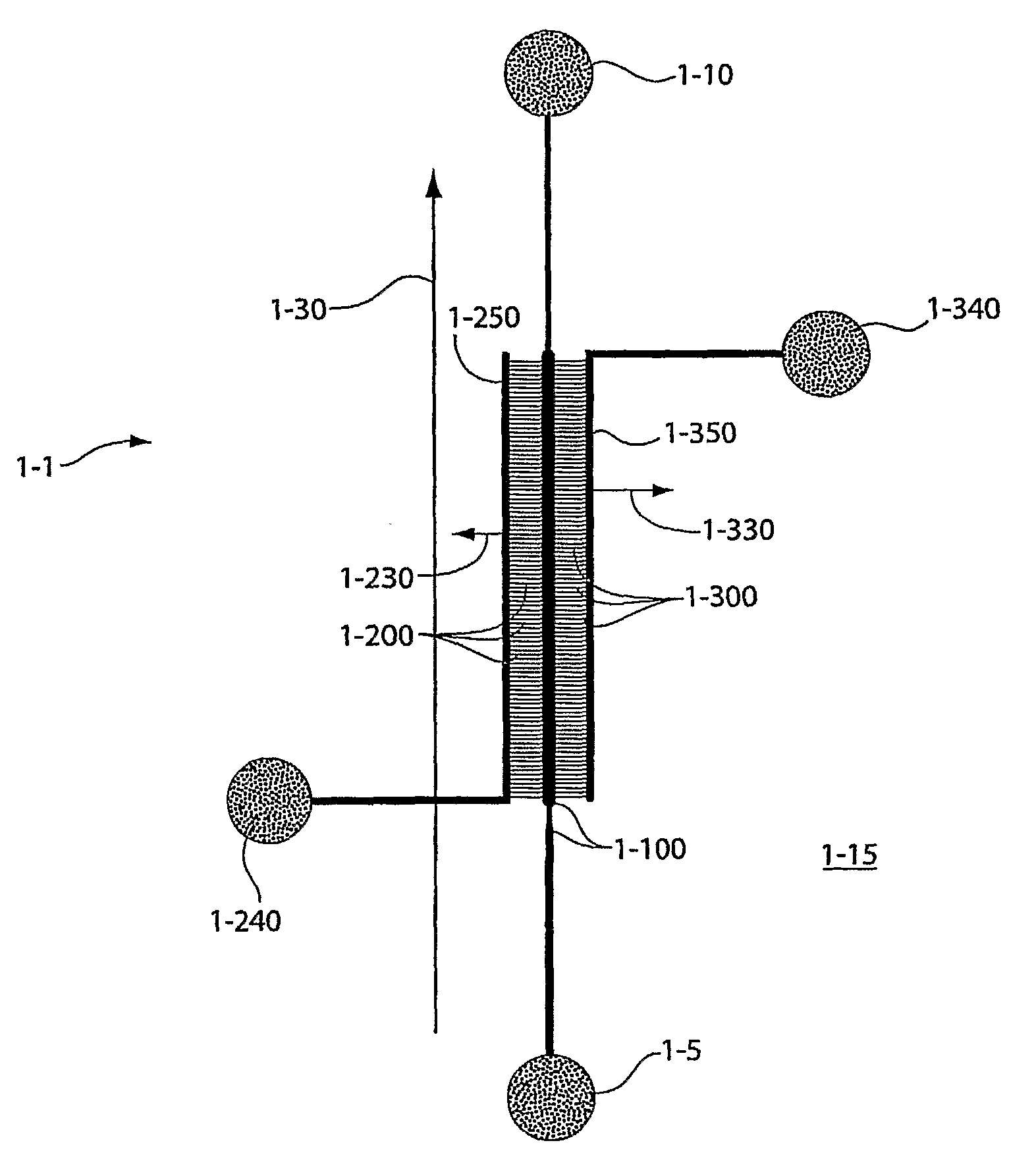
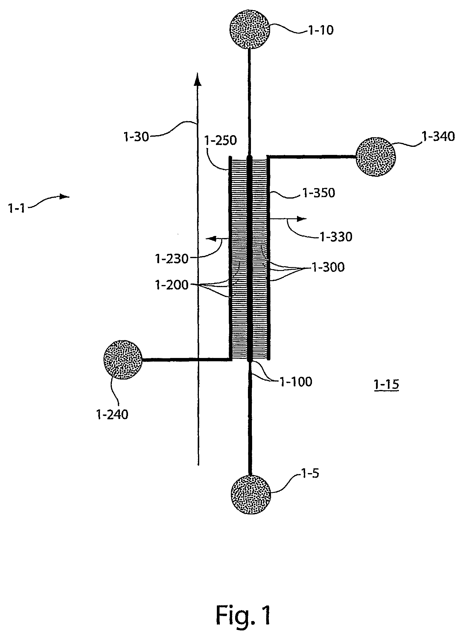
[0063]In one example, a device similar to the one shown in FIG. 1 was fabricated. The device comprised a first channel 1-100, rectangular in cro...

example 2

[0064]Example 2 shows that a suspension of microspheres can be filtered from a fluid using the device of Example 1. A 0.1% w / v suspension of 4 μm fluorescent polystyrene microspheres was introduced into the device via inlet 1-5 and then run at various pressures through the device. Argon from a pressurized gas cylinder was used to apply the driving pressure. FIG. 3 is a close-up (10×) photograph of the device of Example 1, showing entry of the filtrate into secondary channels 3-200 and 3-300. The fluid from the suspension was dyed with 1 mg / mL of fluorescein to improve visibility; the filtrate of the suspension can be seen displacing air 3-260 in the first filtrate collection channel 3-250. In this example, the suspension was driven at a flow rate of 9000 microliters per hour. The microspheres 3-410 can be seen as streaks due to the high flow rate in the first channel 3-100. About 7% of the suspension was extracted as filtrate through the two filtration channels 1-250 and 1-350, and ...

example 3

[0066]The following example demonstrates that porous materials can be formed in the device of Example 1 and that the device comprising the porous materials can be used to filter a sample of whole blood. To form a porous material comprising 1 μm beads, a 0.1% suspension of 1 μm beads was introduced into the device via an inlet to a first main channel. The suspension was flowed through the device using argon from a pressurized gas cylinder. FIG. 5 (63× magnification of the actual device) shows porous layers 5-410, 5-415 and 5-420 being formed in secondary channels 5-200, 5-205, 5-210 at the junction, or interface, of first channel 5-100. The porous layers were formed from random close packing of the spherical beads in different configurations in the channels. For instance, in some cases, the spheres 5-405 packed at the inlet of a secondary channel 5-210. In other cases, the spheres 5-405 comprising porous layer 5-420 packed inside a portion of secondary channel 5-210.

[0067]After the p...


PUM

PropertyMeasurementUnit
Pore sizeaaaaaaaaaa
Flow rateaaaaaaaaaa
Diameteraaaaaaaaaa

Abstract

The present invention includes a microfluidic filter and concentrator that can separate a filtrate from a fluid containing components, e.g. a suspension of particles, to be removed from the fluid at least to some extent. The filter may employ principals of tangential flow filtration, also known as cross-flow filtration. In one aspect, a microfluidic filter described herein includes at least a first, main channel and one or more secondary, filtering channels that connect to the main channel. Filtration occurs when a fluid portion of a sample that is flowed through the main channel enters one or more of the filtering channels and at least some of the components in the sample do not enter or do not flow through the secondary, filtering channels. The secondary channels may be dimensioned to inhibit flow of components through them, and/or a porous material such as a layer may be positioned to inhibit flow of components through the secondary channels.

Description

FEDERALLY SPONSORED RESEARCH[0001]Various aspects of the present invention were sponsored by the National Science Foundation, grant no. DMR-0213805. The Government may have certain rights in the invention.FIELD OF INVENTION[0002]The invention relates to methods and apparatuses for filtration, and / or concentration of fluids such as suspensions and, in particular, to filtration and concentration via tangential flow.BACKGROUND[0003]Fluidic systems, including microfluidic systems, have found application in a variety of fields. These systems that typically involve controlled fluid flow through one or more microfluidic channels can provide unique platforms useful in both research and production. For instance, one class of systems can be used for analyzing very small amounts of samples and reagents on chemical “chips” that include very small fluid channels and small reaction / analysis chambers. Microfluidic systems are currently being developed for genetic analysis, clinical diagnostics, dr...

Claims


Application Information

Patent Timeline
IPC IPC(8): B01D15/34B01D35/00B01D57/00B01D67/00B01D24/02
CPCB01D61/18B01D63/081B01D67/0034B01D2325/028B01D63/088B01D71/70B01D2323/24B01L3/5027B01D71/701
Inventor BALA SUBRAMANIAM, ANANDABKARIAN, MANOUKFABRE, ADRIENDURAND, MARCSTONE, HOWARD A.
Owner PRESIDENT & FELLOWS OF HARVARD COLLEGE
Why Eureka
Try Eureka