Buck-Boost Switching Voltage Regulator

Inactive Publication Date: 2009-04-23
ADVANCED ANALOGIC TECHNOLOGIES INCORPORATED
View PDF4 Cites 203 Cited by
  • Summary
  • Abstract
  • Description
  • Claims
  • Application Information

AI Technical Summary

Benefits of technology

[0017]One comparator output turns switch A and switch B ON and OFF out of phase with each other. The second comparator output turns switch C and switch D ON and OFF out of phase with each oth

Problems solved by technology

In the real world, this is never quite the case.
It takes time to turn the switches ON and OFF and control cannot be done with absolute precision.
But neither type of regulator operates beyond this limit.
This means that Buck regulators and Boost regulators are capable of only regulating a voltage above or below a given input but are not capable of both step u

Method used


Image

  • Buck-Boost Switching Voltage Regulator
  • Buck-Boost Switching Voltage Regulator
  • Buck-Boost Switching Voltage Regulator

Examples


Embodiment Construction

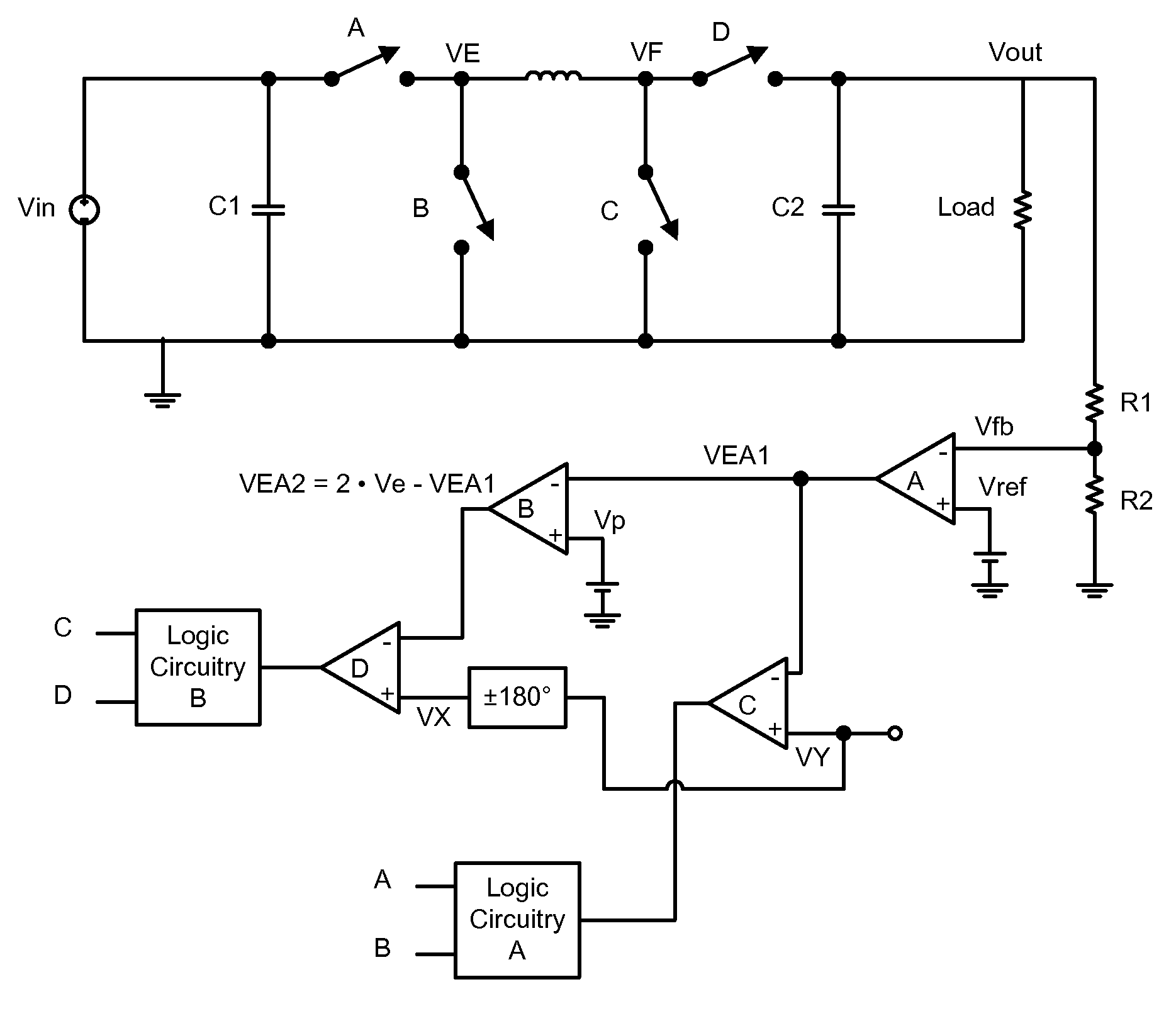
[0029]An embodiment of the present invention includes a Buck-Boost voltage regulator. As shown in FIG. 2, a representative implementation of this regulator includes four switches labeled A, B, C and D. Typically, these switches are MOSFET devices with A and D being PMOS devices and B and C being NMOS devices. It should be appreciated however, that other technologies and device types may be used. Switch A is connected between an input supply (labeled Vin) and a node VE. Switch B is connected between the node VE and ground. An inductor (labeled L) connects the node VE to a node VF. Switch C is connected between the node VF and ground. Switch D connects the node VF to an output node Vout. A load (represented by a resistor) connects the output node to ground. Two capacitors are included. The first or input capacitor is connected between the input voltage and ground. The second or output capacitor is connected between the output node (Vout) and ground. The two capacitors are labeled C1 a...


PUM


Abstract

A buck-boost switching regulator includes two buck switches and two boost switches. Two ramp voltages VY and VY are generated. The voltage VY is compared to a voltage VEA1 that is proportional to the output of the switching regulator. This defines the duty cycle of the two buck switches. The voltage VX is compared to a voltage VEA2 that is inversely proportional to the output of the switching regulator. This defines the duty cycle of the two boost switches. The regulator seamlessly transitions between Buck, Boost and Buck-Boost modes depending on input and output conditions.

Description

BACKGROUND OF THE INVENTION [0001]Switching regulators are intended to be efficient machines for converting a power source from one form to another. The two most common types of switching regulators are Boost (output voltage greater than input voltage) and Buck (output voltage less than input voltage) regulators. Both Boost and Buck regulators are very important for battery powered applications such as cellphones. This particular application relates to a third type of switching regulator where the output voltage can be greater or less than the input voltage. This third type of regulator is known as a Buck-Boost regulator.[0002]As shown in FIG. 1A, a traditional implementation for a Buck regulator includes a switch M1 connected between an input voltage (VBATT in this case) and a node VX. A switch M2 is connected between the node VX and ground. An inductor L is connected between VX and the output node (VOUT) of the regulator. A filtering capacitor connects VOUT to ground. The node VOU...

Claims


Application Information

Patent Timeline
IPC IPC(8): G05F1/10
CPCH02M3/1582
Inventor COLES, CHARLES
Owner ADVANCED ANALOGIC TECHNOLOGIES INCORPORATED
Why Eureka
Try Eureka