
Short pulse/stepped frequency radar system

a radar system and short pulse technology, applied in the field of radar systems, can solve the problems of limited dynamic range, low average power, and high processing load of coherent processing, and achieve the effects of minimizing range side lobes, high dynamic range, and sufficient energy on targ

Active Publication Date: 2006-11-28
RAYTHEON CO
View PDF14 Cites 4 Cited by
  • Summary
  • Abstract
  • Description
  • Claims
  • Application Information

AI Technical Summary

Benefits of technology

[0011]This novel approach should provide sufficient energy on target, minimize range side lobes, maintain high dynamic range and reduce processing data rates in clutter environment for STTW requirements.

Problems solved by technology

The disadvantages of impulse radars are low average power and limited dynamic range.
In addition coherent processing requires a tremendous processing load.
Unfortunately high bandwidths require long frequency sweeps.
One disadvantage of stepped frequency waveforms or any coded waveform is range sidelobes.
Unfortunately, to discriminate small radar cross-sections that are close to large objects requires large dynamic range and low range sidelobes.
Finally, continuous wave radar systems have not proved effective for STTW applications.

Method used


Image

  • Short pulse/stepped frequency radar system
  • Short pulse/stepped frequency radar system
  • Short pulse/stepped frequency radar system

Examples


Embodiment Construction

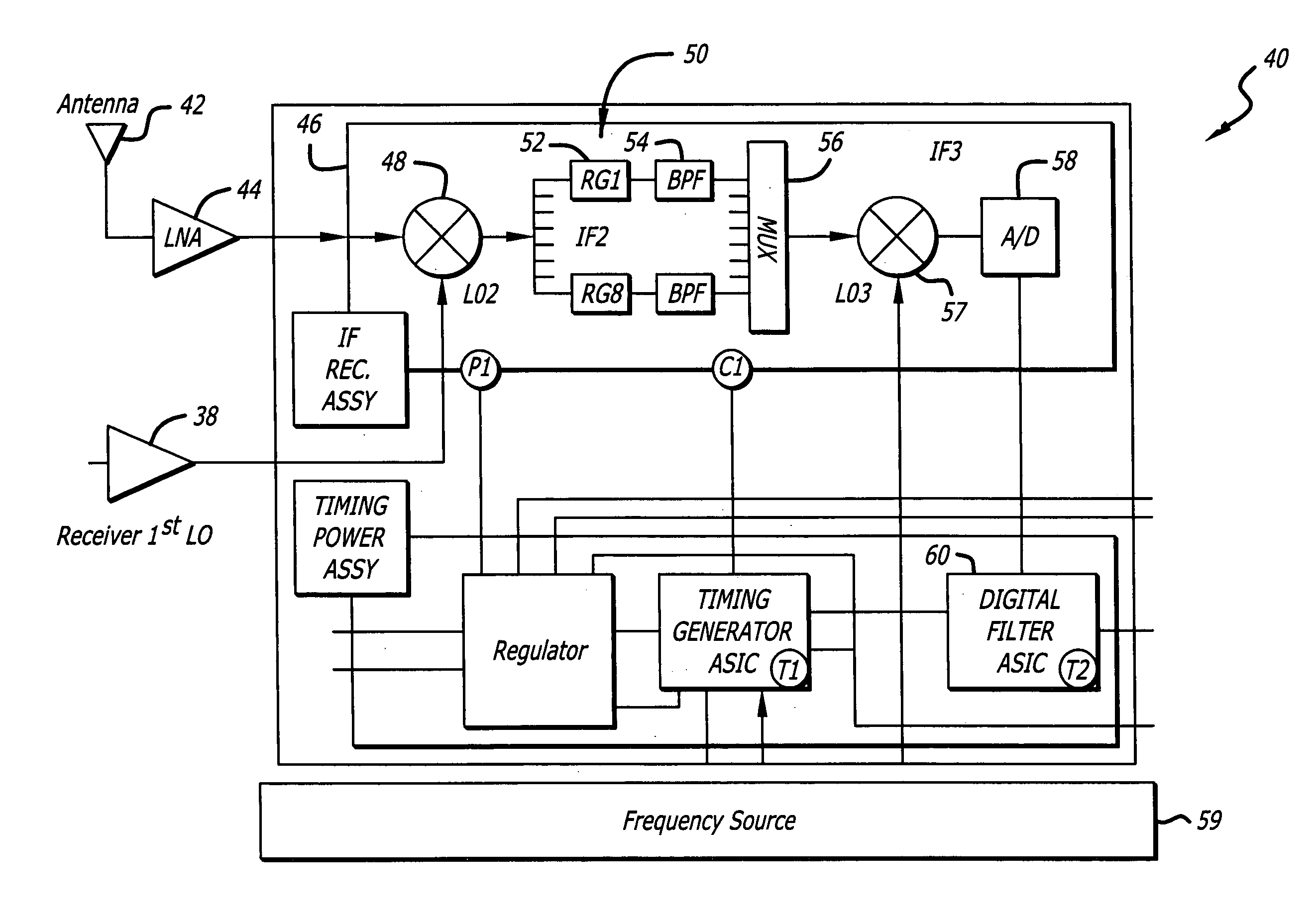
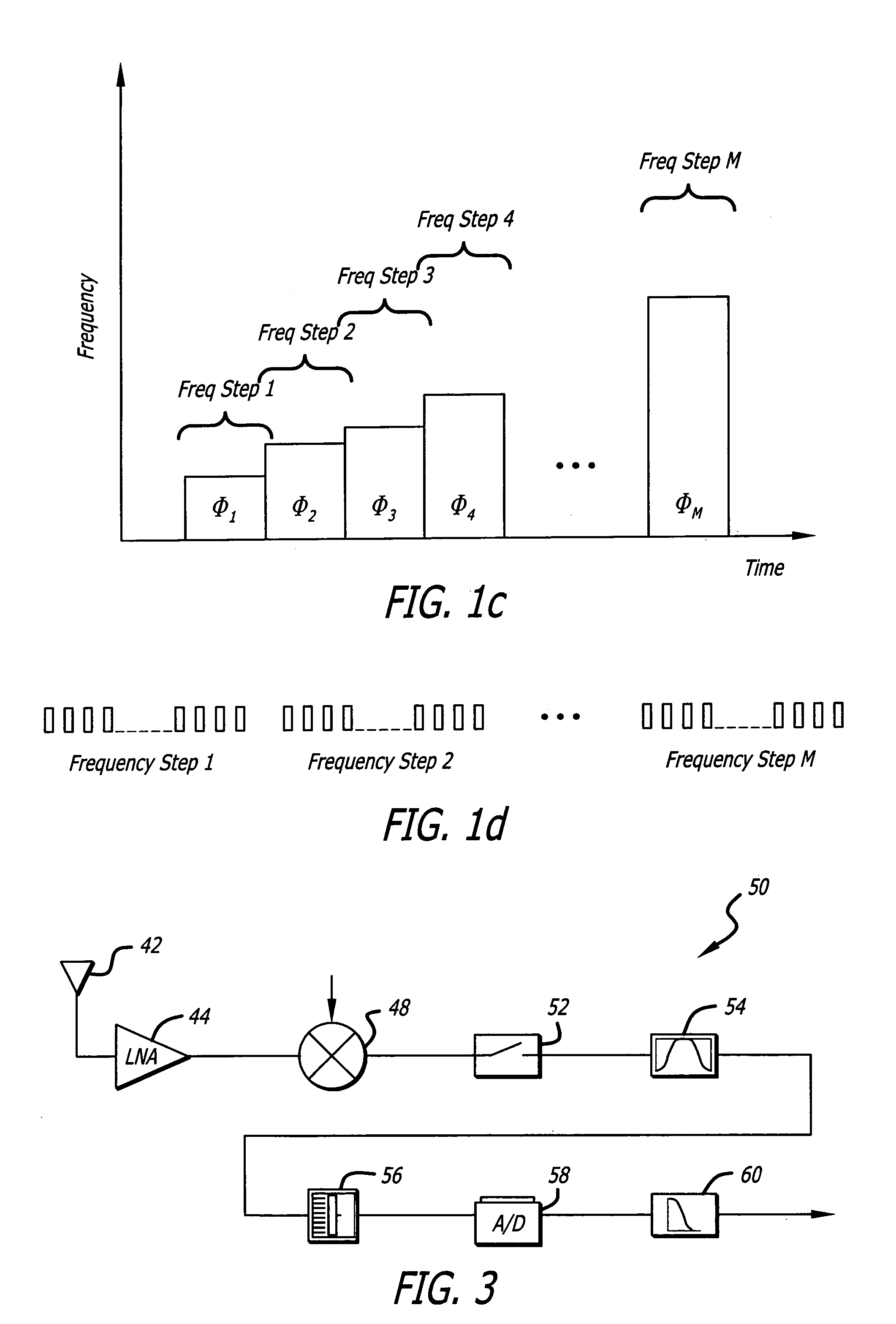
[0021]Illustrative embodiments and exemplary applications will now be described with reference to the accompanying drawings to disclose the advantageous teachings of the present invention.

[0022]While the present invention is described herein with reference to illustrative embodiments for particular applications, it should be understood that the invention is not limited thereto. Those having ordinary skill in the art and access to the teachings provided herein will recognize additional modifications, applications, and embodiments within the scope thereof and additional fields in which the present invention would be of significant utility.

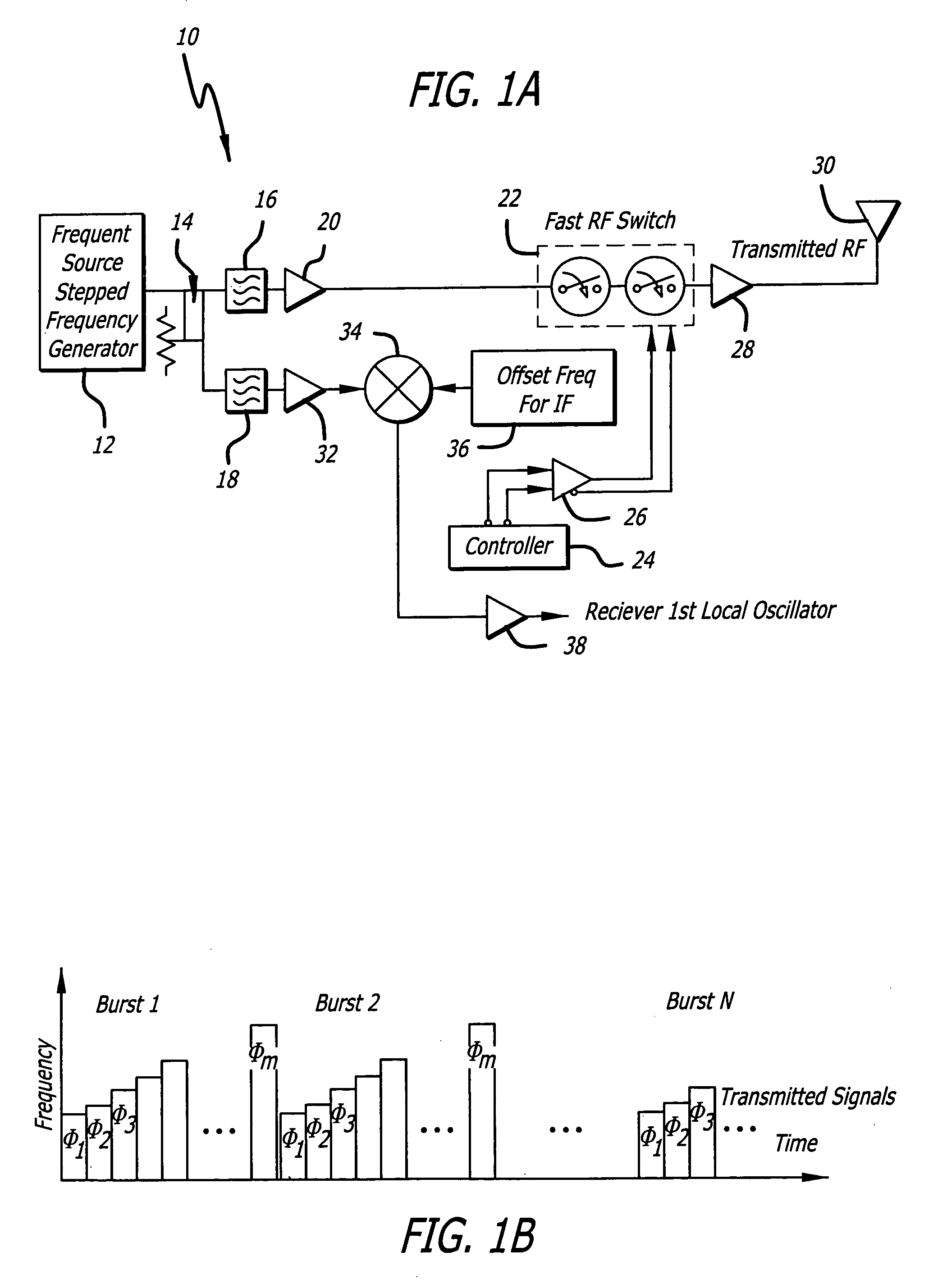
[0023]FIG. 1a is a simplified block diagram of an illustrative implementation of a radar transmitter in accordance with the teachings of the present invention. The transmitter 10 includes a frequency source generator 12 designed to generate a range of frequencies in accordance with the present teachings. The source generator 12 may be implemented in ...


PUM


Abstract

A unique hardware architecture that combines short pulse, stepped frequency and centerline processing. The inventive architecture implements a radar system having a transmitter for transmitting short pulses, each pulse being stepped in frequency and a receiver receiving the pulses and providing an output signal in response thereto. In the illustrative embodiment, the transmitter includes a frequency source, an RF switch coupled to the source and a controller for controlling the RF switch. The receiver includes a signal processor implemented with a center line roughing filter. The signal processor has multiple channels each of which has a range gate and a digital filter. The digital filter includes a Fast Fourier Transform adapted to output a range Doppler matrix.

Description

BACKGROUND OF THE INVENTION[0001]1. Field of the Invention[0002]The present invention relates to electrical and electronic circuits and systems. More specifically, the present invention relates to radar systems.[0003]2. Description of the Related Art[0004]See or Sense Through-the-wall (STTW) sensors and technologies are needed to satisfy current and future operational requirements for an enhanced capability to detect, locate, identify, and classify moving and stationary people or objects through walls, for clearing an urban facility in connection with military, police, security and / or commercial applications. The STTW sensor could be employed by soldiers or by robotic assets (air and ground) to provide detailed information on an occupied or unoccupied environment.[0005]Prior approaches have involved impulse radar and swept frequency radar (CHIRP). Impulse radar transmits an ultra short pulse and can be processed with incoherent processing (detector) or coherent processing. The disad...

Claims


Application Information

Patent Timeline
Patent Type & Authority Patents(United States)
IPC IPC(8): G01S13/26G01S7/28G01S13/00G01S13/02G01S13/32
CPCG01S13/0209G01S13/32
Inventor DWELLY, WESLEY H.ADAMS, VINH N.
Owner RAYTHEON CO
Learn More