

Methods and apparatus for introducing liquids into microfluidic chambers
a microfluidic system and liquid channel technology, applied in the field of microfluidic systems, can solve the problems of affecting the efficiency of microfluidic system filling, and difficult to remove bubbles from such systems, and achieve the effect of higher energy potential and higher energy potential
- Summary
- Abstract
- Description
- Claims
- Application Information
AI Technical Summary
Benefits of technology
Problems solved by technology
Method used
Image

Examples
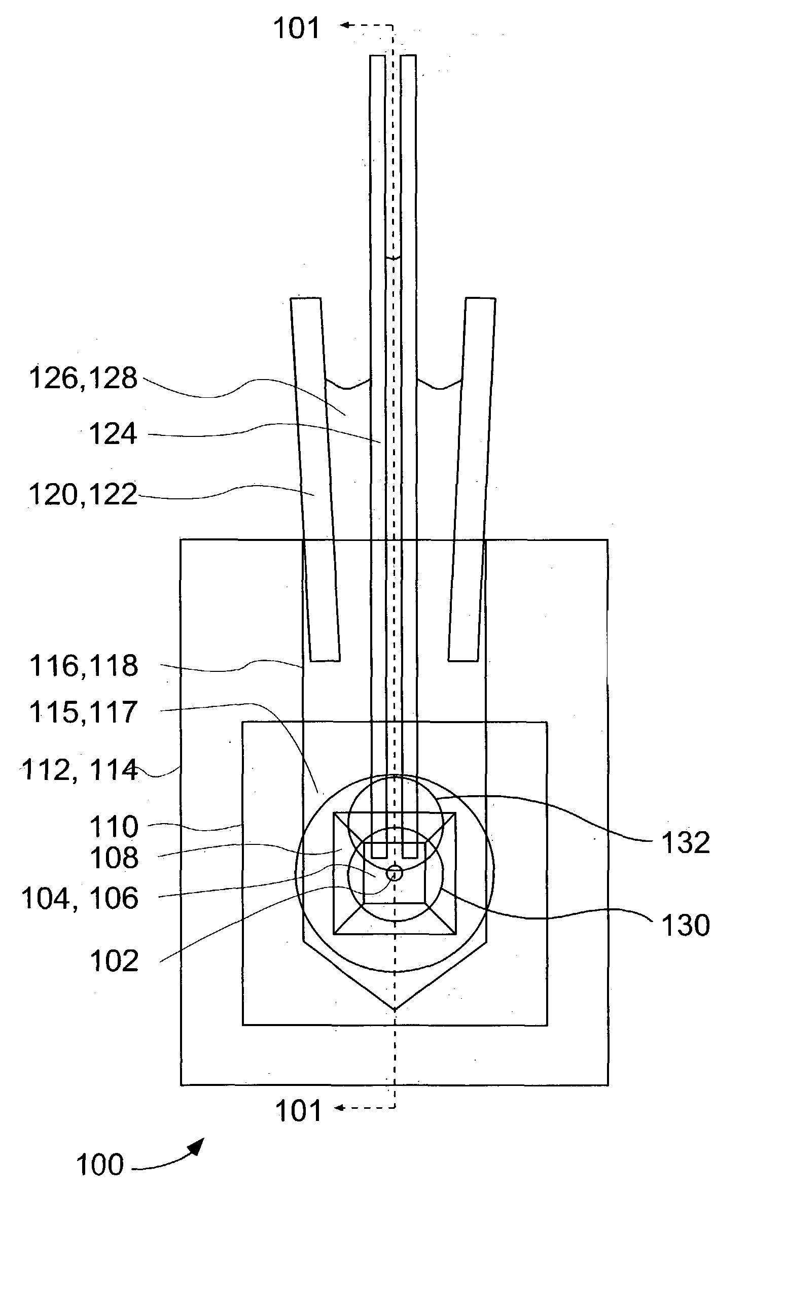
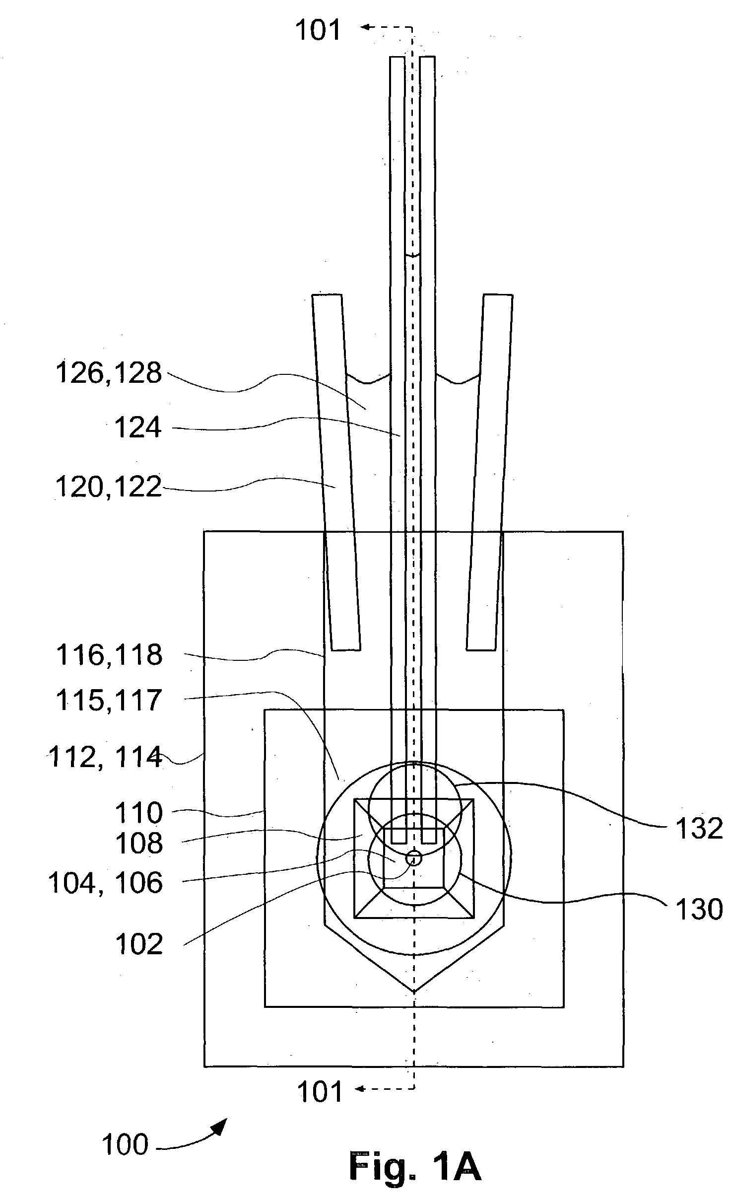
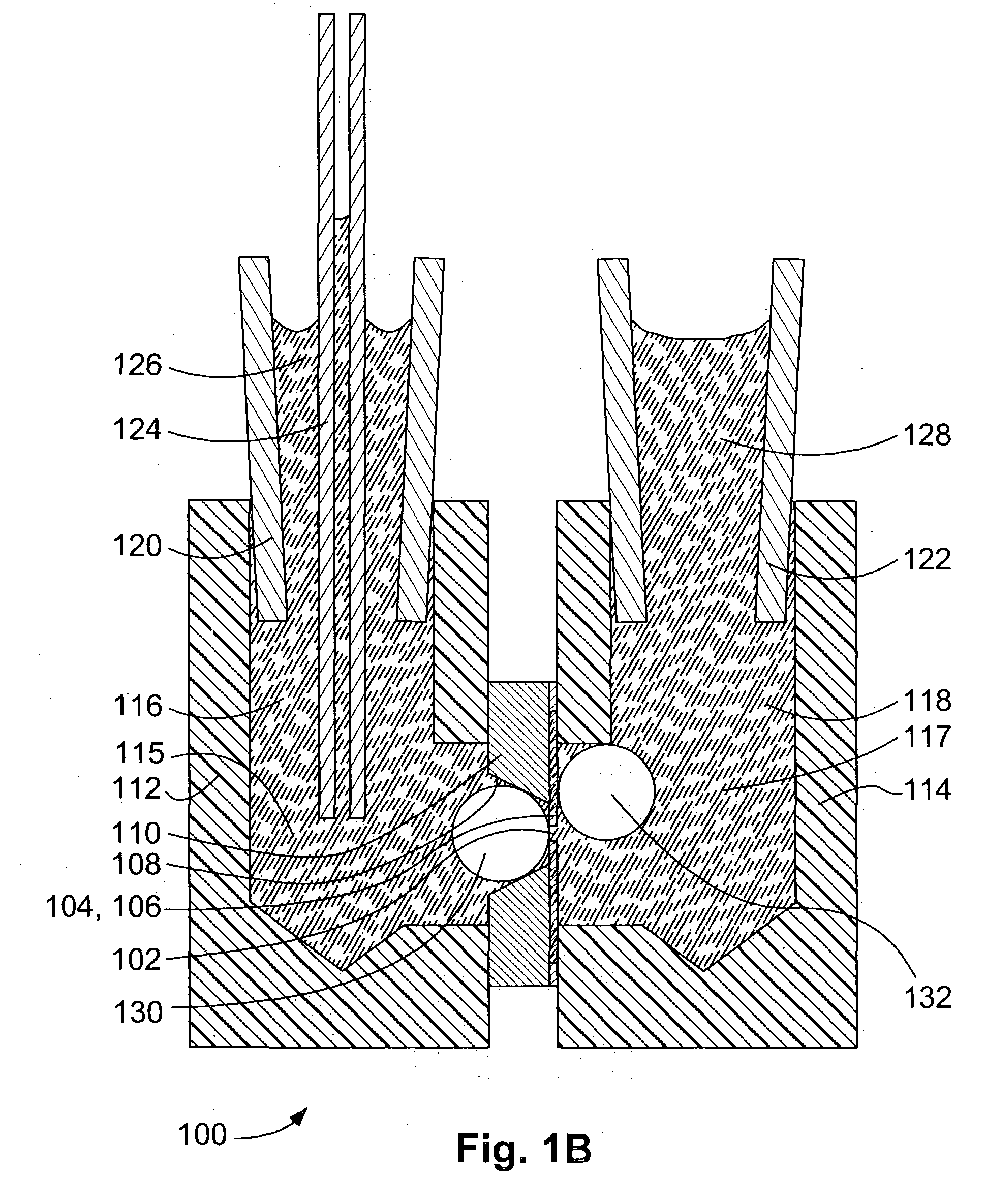
embodiment 100
[0071]FIG. 1D shows embodiment 100 at a time subsequent to the time of FIG. 1C. Ambient atmosphere 133 has been further reduced in pressure, and bubbles 130 and 132 have further expanded in volume. Bubble 130 fills a volume 134. Channel 136 comprises a source channel for liquid, narrow region 138 comprises a barrier region, and channel 140 and ambient gaseous volume 142 comprise an exit region.
[0072]FIG. 1E shows embodiment 100 at a time subsequent to the time of FIG. 1D. Ambient atmosphere 133 has been further reduced in pressure, and bubbles 130 and 132 have further expanded in volume. Bubble 130 has expanded past the narrow barrier region 138, and the radii of curvature of bubble boundary 144 are increasing as this boundary moves up in channel 140.
[0073]FIG. 1F shows embodiment 100 at a time subsequent to the time of FIG. 1E. Ambient atmosphere 133 has been further reduced in pressure, and bubble 132 has expanded further in volume. But bubble 130 has burst at boundary 144, and t...
embodiment 200
[0077] In embodiment 200 as illustrated in FIGS. 2A and 2B, firing chamber 202 comprises firing chamber volume 202a, which is surrounded by firing chamber walls 203. Piezoelectric actuator 204 is adjacent to wall area 205 and, during normal operation of the inkjet, causes ink to be ejected from firing orifice 206 to a substrate, not shown, such as paper or glass. Liquid 207, for example, ink, is supplied to firing chamber 202 through orifice 208 from source channel 210. For purposes of the present invention, barrier orifice 212 and an exit region comprising aperture 214 and ambient volume 215 are included with the inkjet firing chamber. Region 216 may be occupied in part by gaseous bubble 218, which is present in spite of careful filling procedures, or which originates within the liquid 207 because of outgassing of dissolved gas. Gaseous bubble 218 can prevent the inkjet from firing because it introduces a gas elasticity to the system; the situation is similar to the problem of air ...
PUM
| Property | Measurement | Unit |
|---|---|---|
| diameter | aaaaa | aaaaa |
| internal diameter | aaaaa | aaaaa |
| length | aaaaa | aaaaa |
Abstract
Description
Claims
Application Information