Mapping and ablation catheter system

Active Publication Date: 2013-09-17
MAYO FOUND FOR MEDICAL EDUCATION & RES
View PDF11 Cites 71 Cited by
  • Summary
  • Abstract
  • Description
  • Claims
  • Application Information

AI Technical Summary

Benefits of technology

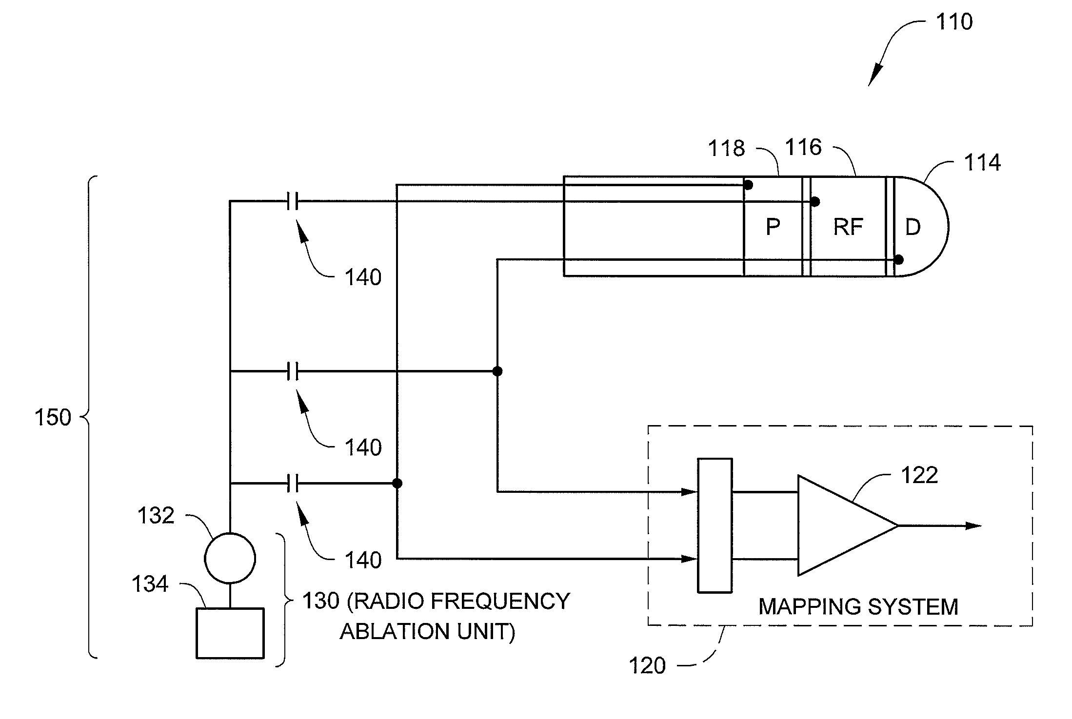
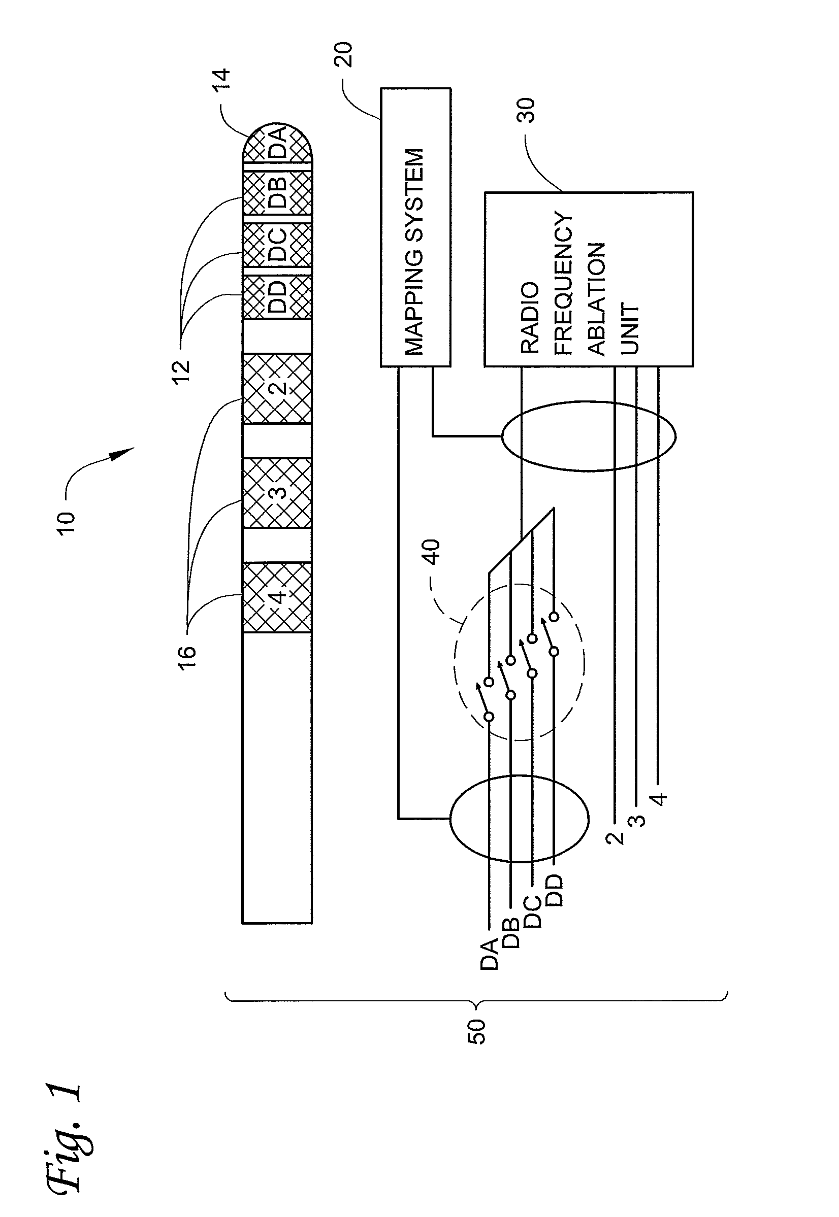
[0011]In various embodiments, one or more of the following features may be included in the systems of the present disclosure: a sheath capable of partially surrounding the catheter and sliding along the catheter to selectively expose one or more of the two or more catheter electrodes (the sheath may include one or more sheath electrodes located on an exterior surface of the sheath, wherein the one or more sheath electrodes are electrically coupled to the mapping device); a return electrode electrically coupled to the radio frequency ablation source; the capacitive components electrically may isolate the radio frequency ablation source from the two or more catheter electrodes when the radio frequency

Problems solved by technology

The requirements of an ideal mapping electrode, however, are different from those of an ideal ablation electrode.
When a small (e.g., short in length) electrode tip is used to ablate tissue, tissue temperature can rise very quickly, but too little power may be delivered to the tissue to effectively produce a lesion.
Most commonly, the 5 mm tip is use

Method used


Image

  • Mapping and ablation catheter system
  • Mapping and ablation catheter system
  • Mapping and ablation catheter system

Examples


Embodiment Construction

[0016]In the following detailed description of illustrative embodiments of the systems, reference is made to the accompanying figures of the drawing which form a part hereof, and in which are shown, by way of illustration, specific embodiments in which the systems may be provided. It is to be understood that other embodiments may be utilized and structural changes may be made without departing from the scope of the present disclosure.

[0017]The words “preferred” and “preferably” as used herein refer to embodiments that may afford certain benefits, under certain circumstances. However, other embodiments may also be preferred, under the same or other circumstances. Furthermore, the recitation of one or more preferred embodiments does not imply that other embodiments are not useful, and is not intended to exclude other embodiments.

[0018]As used herein, “a,”“an,”“the,”“at least one,” and “one or more” are used interchangeably. The term “and / or” (if used) means one or all of the identifie...


PUM


Abstract

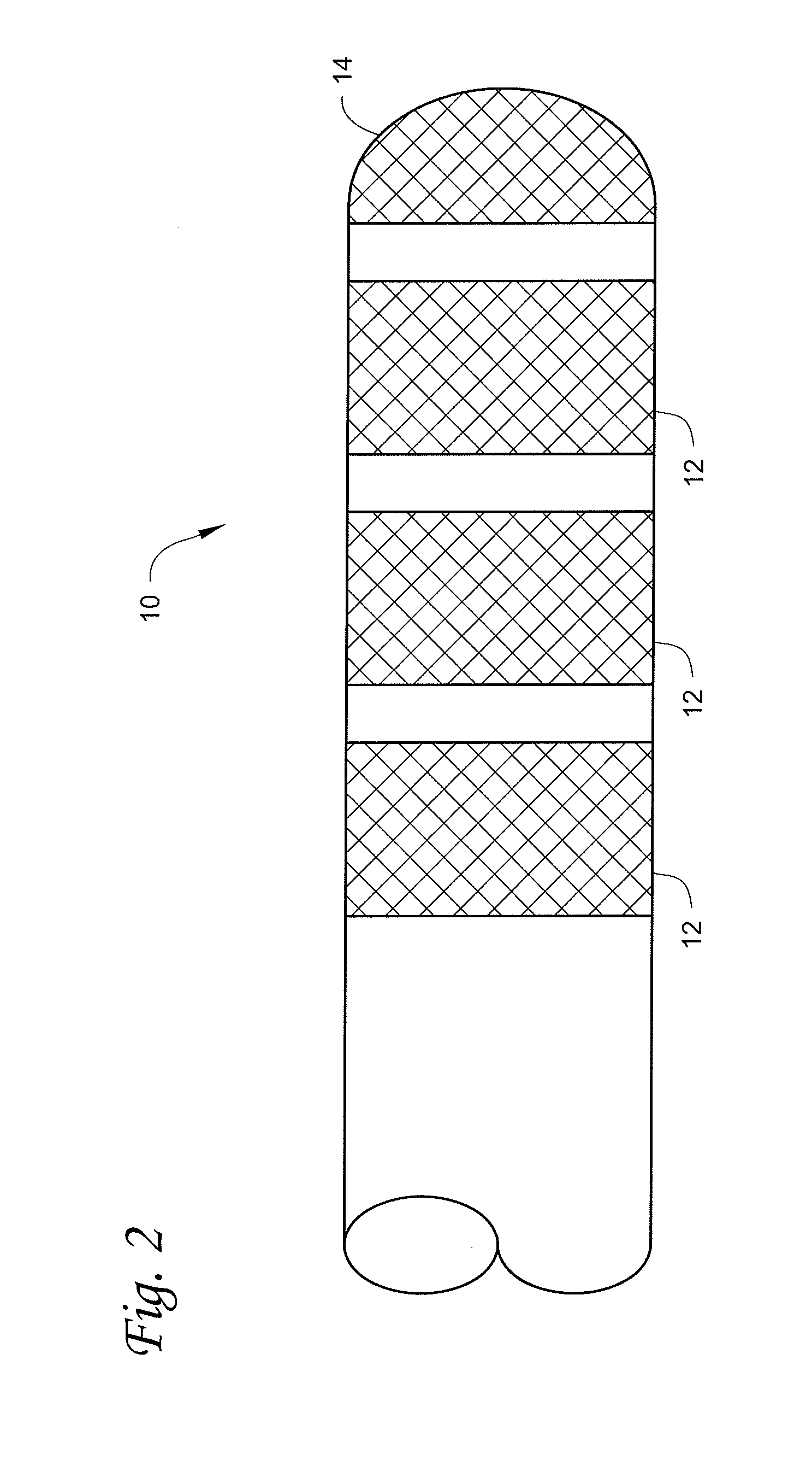
A mapping and ablation catheter system including a radio frequency ablation source having an output, a mapping device, a catheter, and two or more capacitive components. The catheter may include two or more catheter electrodes, wherein two of the two or more catheter electrodes may be electrically coupled to the mapping device. Each of the two or more catheter electrodes may be electrically coupled to a capacitive component, wherein each capacitive component may be electrically coupled to the output of the radio frequency ablation source such that energy delivered to each catheter electrode of the two or more catheter electrodes passes through the capacitive component.

Description

RELATED APPLICATION[0001]The present application is a U.S. National Stage Application of International Application No. PCT / US2009 / 030548, titled MAPPING AND ABLATION CATHETER SYSTEM, filed on Jan. 9, 2009, published in the English language on Jul. 16, 2009 as International Publication No. WO 2009 / 089415 A1, which claims the benefit under 35 U.S.C. §119(e) of U.S. Provisional Patent Application No. 61 / 010,519, filed on Jan. 9, 2008, titled MAPPING AND ABLATION CATHETER SYSTEM, both of which are hereby incorporated by reference in their entirety.[0002]The present invention relates generally to cardiac mapping and ablation catheter systems.[0003]The systems described herein may be used in the mapping and ablation of tissue associated with tachyarrhythmia. In some embodiments, the systems include a catheter that may include one or more electrodes located about the distal end of the catheter. The catheter may be manipulated within one or more cardiac chambers to obtain electrograms from ...

Claims


Application Information

Patent Timeline
IPC IPC(8): A61B5/042A61B18/14
CPCA61B5/042A61B5/6852A61B18/1492A61B5/01A61B18/1233A61B2018/00083A61B2018/0016A61B2018/00196A61B2018/00357A61B2018/00654A61B2018/00797A61B2018/00839A61B2018/124A61B2018/1467A61B2018/1472A61B2218/002A61B5/283
Inventor VENKATACHALAM, KALPATHIASIRVATHAM, SAMUEL J.
Owner MAYO FOUND FOR MEDICAL EDUCATION & RES
Why Eureka
Try Eureka