Vibratory system for a sorting flow cytometer

a flow cytometer and vibrating system technology, applied in the field of flow cytometer system, to achieve the effect of easy movement out of the way

Inactive Publication Date: 2004-06-08
DAKO COLORADO +1
View PDF9 Cites 75 Cited by
  • Summary
  • Abstract
  • Description
  • Claims
  • Application Information

AI Technical Summary

Benefits of technology

The present invention includes a variety of aspects which may be selected in different combinations to suit the needs of the user. First, it can function as a nozzle unclogging tool or cleaning tool for a cytometer nozzle or any nozzle which has been partially clogged. Second, it can be used as an unclogging tool for a cytometer nozzle or any nozzle which has become fully clogged or has a particle entrapped. In a basic form, the concept involves taking a source of vibratory energy or using an energy converter which creates mechanical oscillations (as selected with a oscillation selection element or by sweeping a range of oscillations), and with a media or oscillation coupling element present (such as a fluid, gel or other appropriate media) or through a mechanical couple, and transferring the energy from the source and presenting (coupling) it to the problem area or to allow the media in cooperation with the vibration (either ultrasonic or subsonic) to dislodge any matter in the nozzle which may be causing the clog. Such a technique offers advantages to the operator of the cytometer in allowing machine downtime and any resulting realignment to be greatly reduced, thereby making the operation of a cytometer to be more predictable and increasing the likelihood of successfully sorting a particular sample. Third, it can function as a de-bubbling tool to aid the cytometer operator in removing bubbles from a cytometer. This device excites the nozzle and surrounding fluid in such a way that the air quickly migrates to areas where it can be removed. The invention does this by providing a means for a vibratory chamber of media in which to immerse the nozzle, especially the orifice of the nozzle, into the vibrating media in the chamber while the nozzle is still mounted and fluidically attached or by means of mechanical coupling to the exterior surfaceof the nozzle.
Based upon testing which has occurred to date, it functions particularly well on partially clogged nozzles. It appears to typically unclog these nozzles and allow the cytometer stream to return to its original position, thereby eliminating the need for adjustment, so typical prior to the present invention.
One of the broad objects of the invention is to allow for an unclogging tool or portable member configured so as to mechanically couple mechanical oscillations to the exterior of the nozzle to be used while the nozzle is present on the cytometer, in situ. Thus, one goal includes making the device small enough to fit within the existing spaces surrounding the nozzle on cytometers. Another goal would be to allow a means for the device to be moved into position or have a portable member such that the chamber or portable surface configured so as to mechanically couple mechanical oscillations to the exterior of the nozzle is presenting the vibratory media to the nozzle orifice or nozzle exterior and then easily removed from this area such that normal cytometer functions can take place. This goal may be accomplished manually (hand held) such as with a portable device or may be automated with a more permanently mounted unit or automated movement that retracts and engages the nozzle. Likewise, it may be manually activated independent of flow cytometer operation conditions when the operator notices a variation in the processing or it may be automated by sensors detecting a clogging or in response to flow cytometer conditions.
Another goal would be to allow the use of such a device that will not harm the nozzle. A goal for this invention is to unclog the nozzle while preventing any aspects to the procedure which could effect the positioning of the nozzle or the original condition of the nozzle orifice.
Another broad object of the invention is to provide a means of removing air bubbles from the nozzle or debubbling. Some of the goals for this object remain the same as for unclogging in that the device is generally small enough to fit in the space allowed and may be easily moved out of the way after use. A further goal would be to allow the cytometer operator to pull a vacuum on the inside of the nozzle chamber while presenting a surface configured so as to mechanically couple mechanical oscillations to the exterior of the nozzle or a chamber of media to the nozzle and vibrating the media and therefore the nozzle with sufficient energy that any air bubbles in the nozzle will no longer cling to the sides of the nozzle, but will rise to areas where they may removed through fluidic hoses and tubes.
Yet another goal would be to allow for different cytometer nozzles on different cytometer machines to be unclogged and debubbled with this invention. Further, it is a goal to provide this in an economical manner such that it is affordable to the cytometry user.

Problems solved by technology

Second, it can be used as an unclogging tool for a cytometer nozzle or any nozzle which has become fully clogged or has a particle entrapped.

Method used


Image

  • Vibratory system for a sorting flow cytometer
  • Vibratory system for a sorting flow cytometer
  • Vibratory system for a sorting flow cytometer

Examples


Embodiment Construction

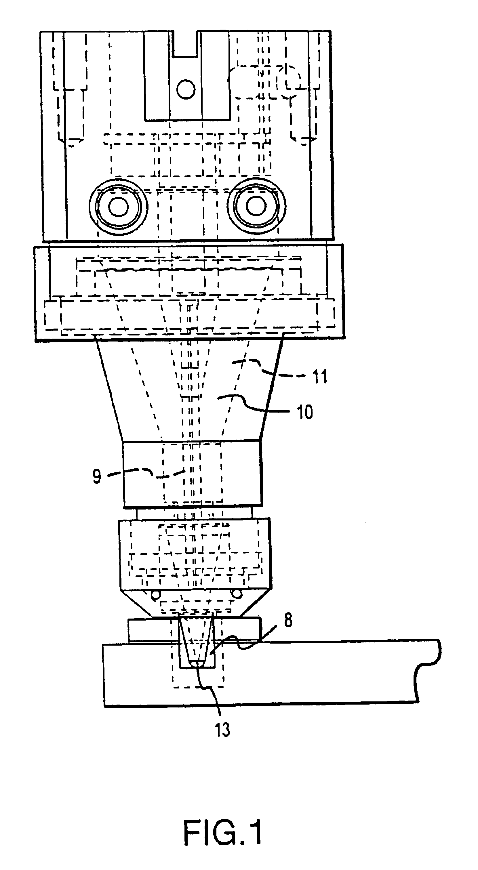
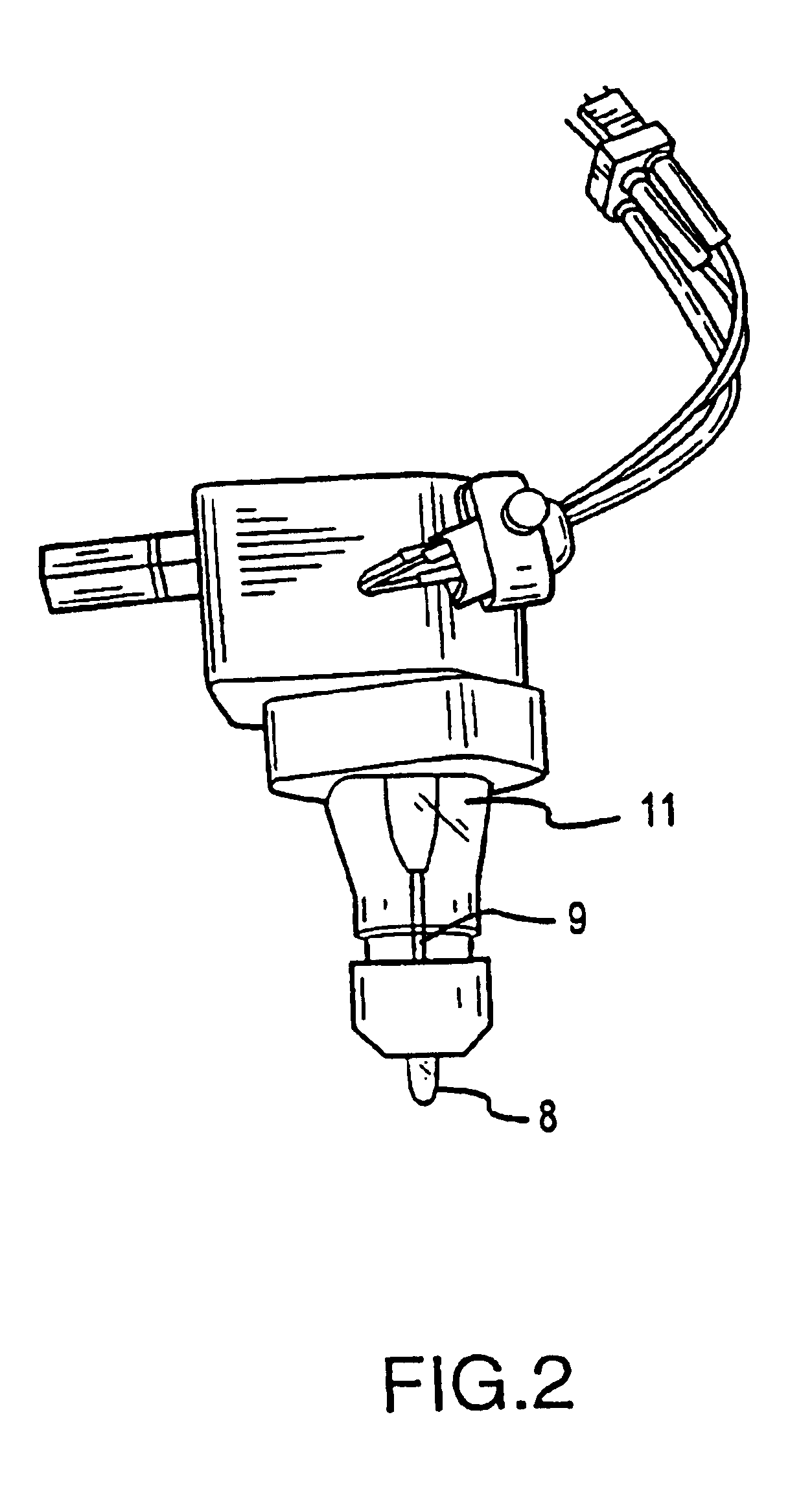
The preferred embodiment is that of a probe or portable member which includes a surface configured to mechanically couple oscillation to the exterior of the flow cytometer nozzle or a cavity which holds a media (such as a fluid, gel, or other appropriate energy transferring media) which creates a bath or oscillations coupling element which may be vibrating. This cavity is presented to the nozzle, especially the orifice area, and allows the nozzle orifice to be at least partially immersed into the bath where any undesirable material may be removed or cleaned or the energy may be used for other purposes such as removing air bubbles from the nozzle.

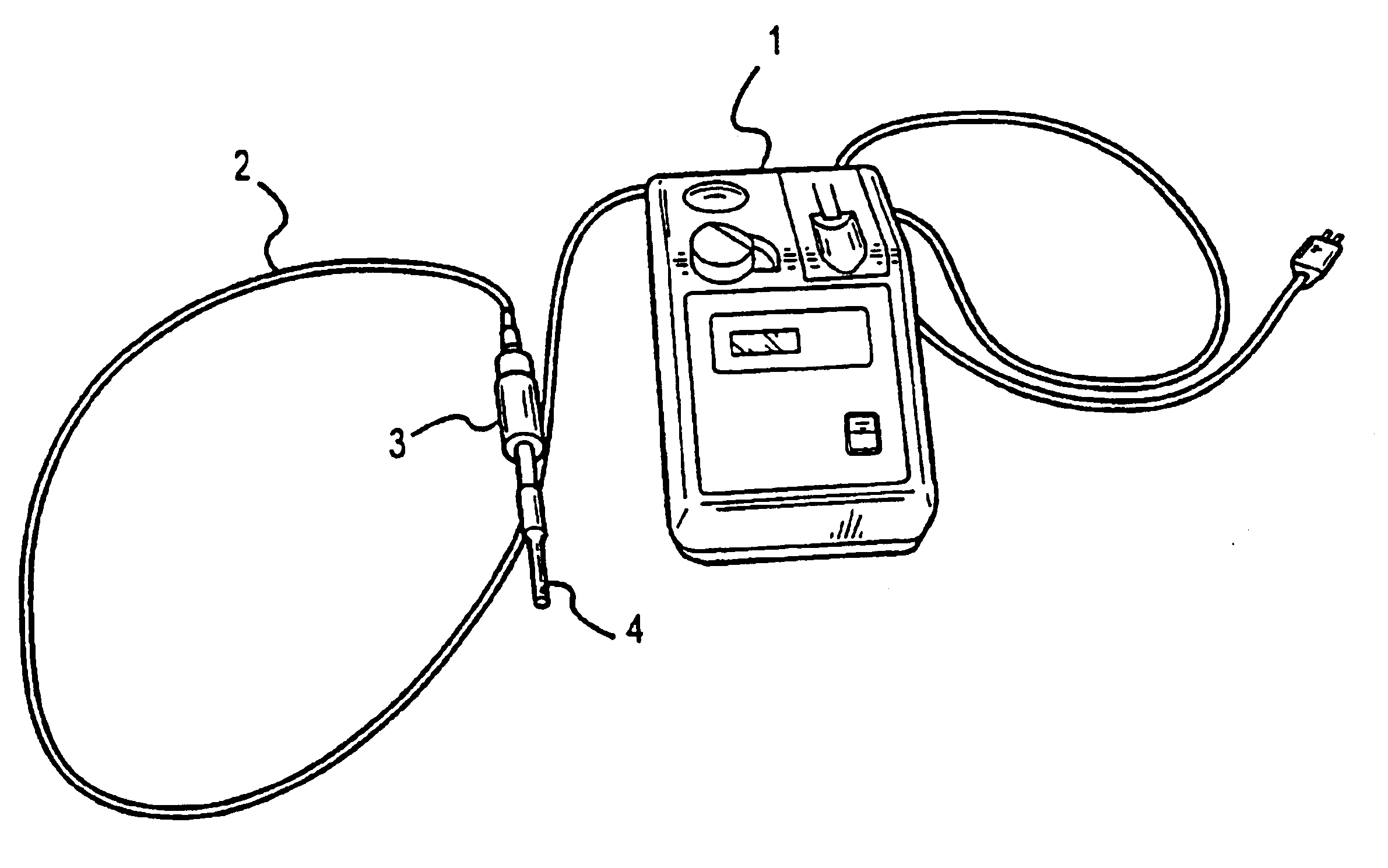
As shown in FIG. 4, part of the unit involves a source of vibrating energy, or vibration generator or energy converter (1), available from a variety of suppliers as would be known to those of ordinary skill in the art. This generator may develop a variety of frequencies of selected or varying amplitudes designed to optimally excite the probe...


PUM

PropertyMeasurementUnit
diameteraaaaaaaaaa
lengthaaaaaaaaaa
heightaaaaaaaaaa

Abstract

A flow cytometry system is disclosed for oscillating the exterior of a flow cytometer nozzle. Oscillating the exterior of a flow cytometer nozzle at selected oscillations or a sweeping range of oscillations disintegrates particles and gas entrapped within the flow cytometer nozzle. Adherents absorbed to the exterior of the flow cytometer nozzle may also be removed. An energy source (1) serves to generate a selected oscillation or range of oscillations. The energy source (1) is connected to a flexible transfer element (2) which conducts the electrical signals to an oscillation system (3). The oscillation system (3) turns the electrical energy from the energy source (1) into mechanical oscillations and is connected to a portable device (4) which disintegrates particles, dislocates gas within the flow cytometer nozzle and cleans the exterior of the flow cytometer aperture.

Description

I. TECHNICAL FIELDThis invention relates to a flow cytometry system and methods of operating both analytical and drop flow cytometers including apparatus and methods of unclogging or dislodging of media or gas from the inside of devices which may become clogged, Specifically, the invention focuses upon a device which may be used to unclog nozzles, dislocate gas, or clean exterior surfaces of flow cytometers used in the cytometry industry, which are subject to clogging, entrapping gas, or collecting adherents to exterior surfaces.II. BACKGROUNDThe desire to unclog, dislocate entrapped gas, and clean nozzles or a nozzle body has been known in some industries for many years. This desire has been quite acute for quite some time in the cytometry field. Cytometers are sometimes used to separate or sort particles from one another based upon the differences detected by shining a high intensity light upon each particle then discerning differences between the amount of light reflected from ea...

Claims


Application Information

Patent Timeline
Patent Type & Authority Patents(United States)
IPC IPC(8): G01N15/14
CPCG01N15/1404G01N2015/1418
Inventor BUCHANAN, KRISTOPHER S.HERICKHOFF, LISASEIDEL, GEORGEMALACHOWSKI, GEORGE C.OTTENBERG, MATTHIAS J. G.FERGUSON, DOUGLAS H.
Owner DAKO COLORADO
Why Eureka
Try Eureka