Ranging system, transmitting terminal, receiving terminal, ranging method, and computer program

a ranging system and receiver technology, applied in the field of ranging systems, can solve the problems of inability to perform ranging between terminals over wireless lans under ieee 802.11a or the like in the household or in a small office, and the error of ranging between terminals is large, so as to achieve the effect of significantly boosting the accuracy of the measured distance between terminals and reducing the appreciable error of ranging between terminals

Inactive Publication Date: 2010-12-28
SONY CORP
View PDF10 Cites 6 Cited by
  • Summary
  • Abstract
  • Description
  • Claims
  • Application Information

AI Technical Summary

Benefits of technology

[0013]The present invention has been made in view of the above circumstances and provides a ranging system, a transmitting terminal, a receiving terminal, a ranging method, and a computer program offering innovations and improvements for reducing ranging errors with multi-carrier transmission systems.
[0016]In one preferred structure of the above-outlined embodiment of the present invention, the impulse responses may constitute time information indicating highly accurate times at which the packets were received and / or transmitted. This preferred structure permits acquisition of precise packet reception and / or transmission times, thereby contributing to more accurate measurement of the distance between terminals.
[0020]Where the transmitting terminal practiced as another embodiment of the present invention is in use, the packet turnaround time is estimated as the time it takes a packet to reach the receiving terminal and to return from there. The estimation is based on the time at which the first packet was transmitted and on the time at which the second packet was received. A highly accurate propagation turnaround time, i.e., the time it takes radio waves to reach the receiving terminal and to return from there, is then obtained on the basis of the internal processing delay time, first impulse response, and second impulse response. This embodiment of the present invention thus makes it possible to acquire propagation turnaround time with precision, whereby ranging error is minimized and accuracy of the measured distance between terminals is maximized even where the multi-carrier transmission system is in use.
[0032]Where the transmitting terminal practiced as a yet further embodiment of the present invention is in use, the packet turnaround time is estimated as the time it takes a packet to reach the receiving terminal and to return from there. The estimation is based on the time at which the first packet was transmitted and on the time at which the second packet was received. A highly accurate propagation turnaround time, i.e., the time it takes radio waves to reach the receiving terminal and to return from there, is then obtained on the basis of the internal processing delay time, first impulse response, and second impulse response. This embodiment of the present invention thus makes it possible to acquire propagation turnaround time with precision, whereby ranging error is minimized and accuracy of the measured distance between terminals is maximized even where the multi-carrier transmission system is in use. Because the transmitting terminal acquires the first and the second impulse responses in unified fashion, the processes associated with ranging are consolidated. It is also possible to make the internal structure of the receiving terminal appreciably simpler than that of the transmitting terminal.
[0037]According to the present invention, as outlined above, the accuracy of the measured distance between terminals under the multi-carrier transmission system is significantly boosted. That is, the ranging error in measuring distances between terminals is reduced appreciably.

Problems solved by technology

It follows that errors tend to be large when ranging is performed on the basis of packet reception times.
Ranging is done with precision only on the order of meters, which means errors can be unacceptably large.
As a result, performing the ranging between terminals over a wireless LAN under the IEEE 802.11a or the like in the household or in a small office has not been practical because of the large errors involved.

Method used


Image

  • Ranging system, transmitting terminal, receiving terminal, ranging method, and computer program
  • Ranging system, transmitting terminal, receiving terminal, ranging method, and computer program
  • Ranging system, transmitting terminal, receiving terminal, ranging method, and computer program

Examples


first embodiment

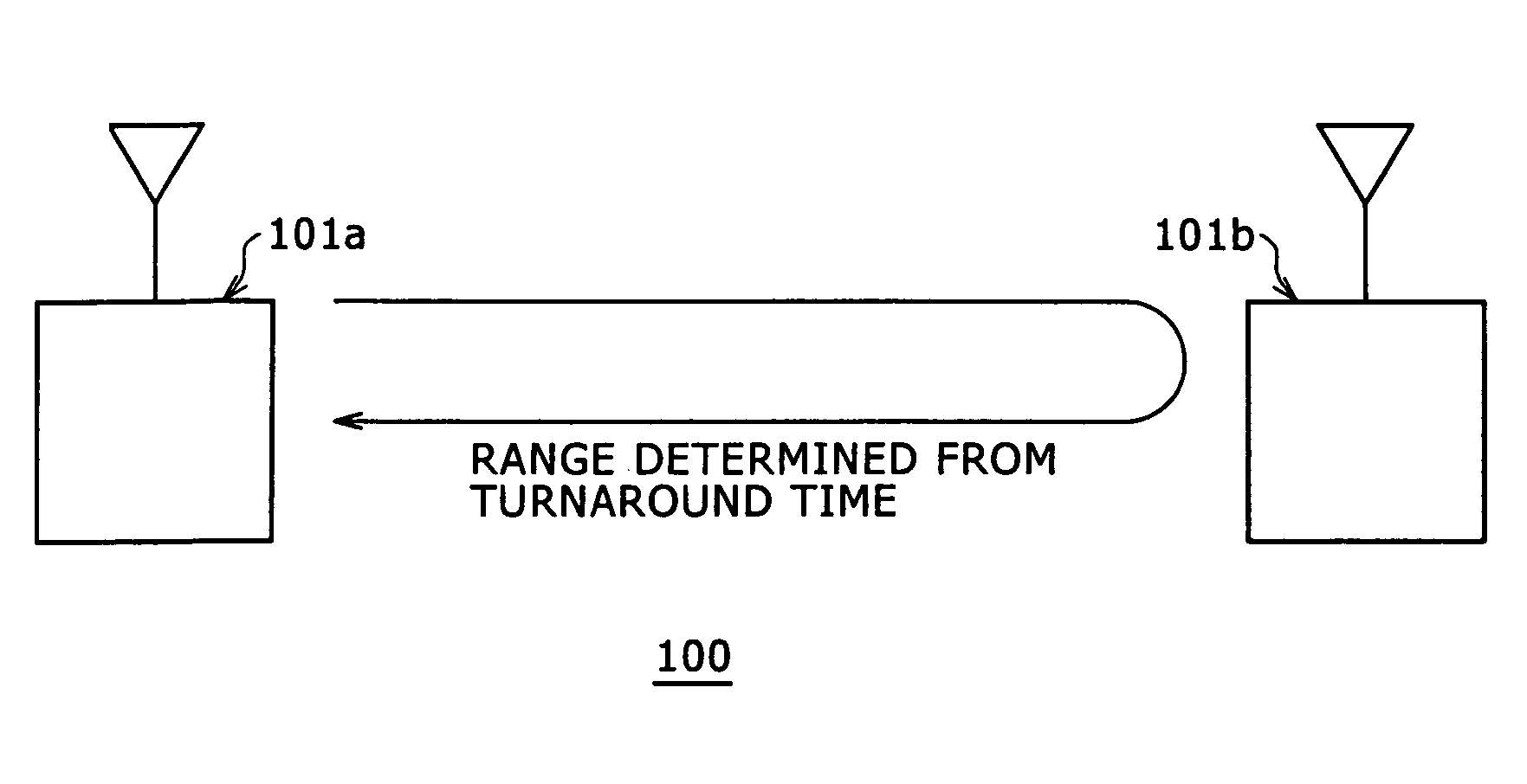
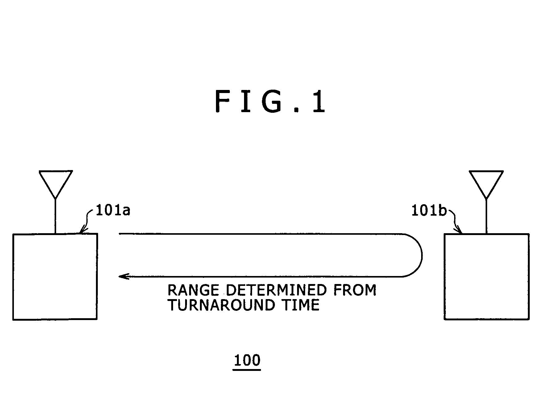
[0052]A ranging system 100 practiced as the first embodiment of the present invention is described below with reference to FIG. 1. FIG. 1 is an explanatory view outlining a typical configuration of the ranging system 100 practiced as the first embodiment.

[0053]As shown in FIG. 1, the ranging system 100 includes at least a transmitting terminal 101a (referred to as the terminal A where appropriate) for initiating a ranging process, and a receiving terminal 101b (referred to as the terminal B where appropriate) being the target of the ranging process. Alternatively, the two terminals may switch their roles. As another alternative, the ranging system may include three or more terminals 101.

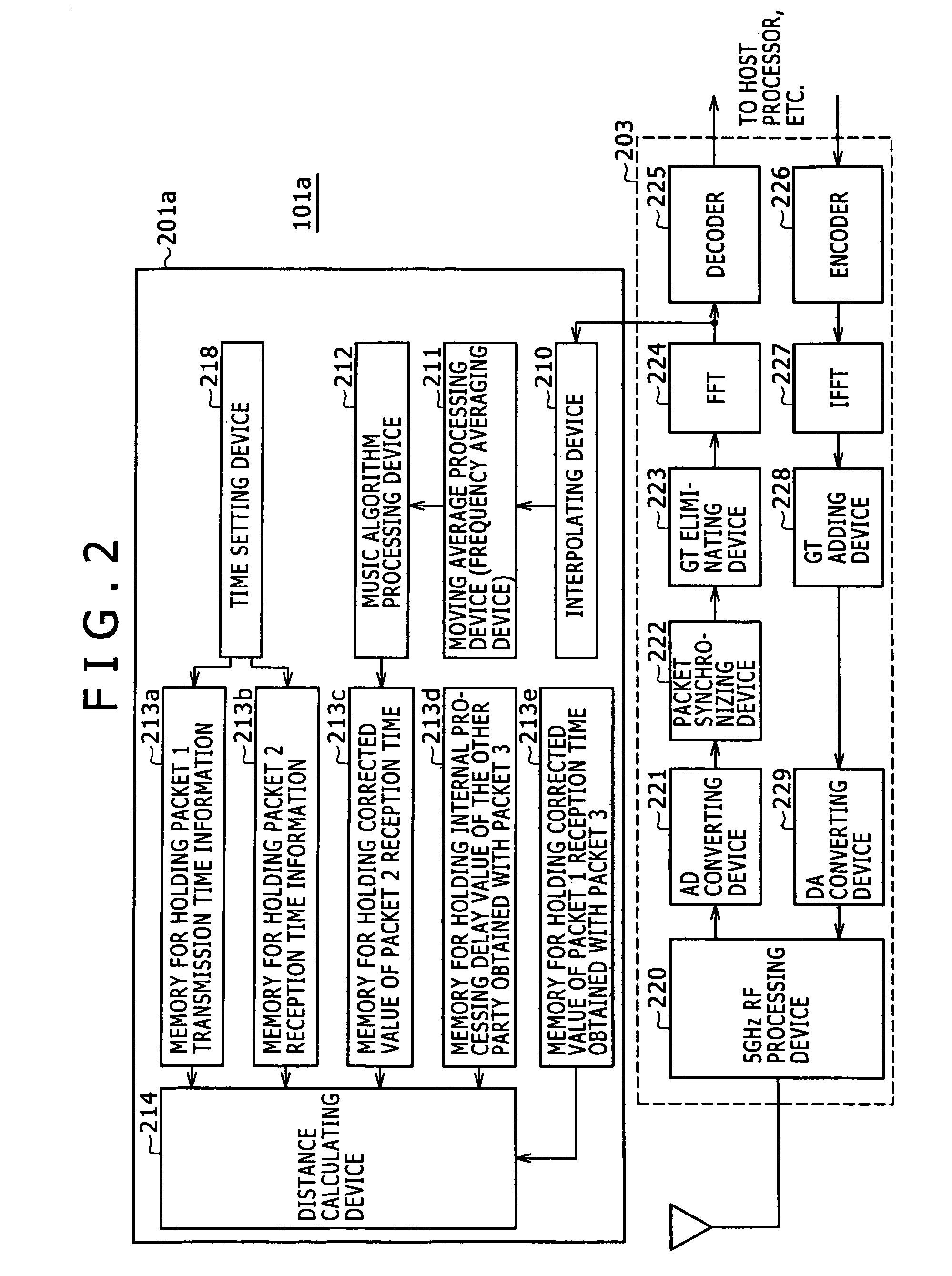
[0054]The terminals 101 of the first embodiment may illustratively be a personal computer (PC) each. Alternatively, any equipment capable of sending and receiving data over a wireless LAN may act as a terminal of the ranging system 100.

[0055]The ranging process of the ranging system 100 in FIG. 1 inv...

second embodiment

[0114]The terminal 101 practiced as the second embodiment of the present invention will now be described with reference to FIGS. 11 and 12. FIG. 11 is a block diagram showing a typical structure of the transmitting terminal (101c) practiced as part of the second embodiment of the invention, the terminal initiating a ranging process, and FIG. 12 is a block diagram showing a typical structure of the receiving terminal (101d) practiced as another part of the second embodiment, the terminal being the target of the ranging process.

[0115]The ranging system of the second embodiment is configured in substantially the same way as the ranging system 100 of the first embodiment explained above with reference to FIG. 1 and thus will not be discussed further in detail. The terminals 101 of the second embodiment will be discussed in detail where they differ from their counterparts of the first embodiment. The resembling aspects of the terminals will not be described further in detail to avoid unn...


PUM


Abstract

A ranging system is disclosed which measures a distance between terminals operating on a multi-carrier transmission system. The ranging system includes a frequency domain data processing device that acquires impulse responses by subjecting data from transmitted and / or received packets to fast discrete Fourier transform for conversion into frequency domain data subject to a predetermined process and by applying a spectrum estimation algorithm to the processed frequency domain data.

Description

CROSS-REFERENCE TO RELATED APPLICATIONS[0001]The present invention contains subject matter related to Japanese Patent Application JP 2004-334632 filed with the Japanese Patent Office on Nov. 18, 2004, the entire contents of which being incorporated herein by reference.BACKGROUND OF THE INVENTION[0002]The present invention relates to a ranging system, a transmitting terminal, a receiving terminal, a ranging method, and a computer program for use with a multi-carrier transmission system.[0003]It is common knowledge that a plurality of computers are connected by suitable telecommunication means to constitute a wireless local area network (LAN) over which files and data are exchanged and shared wirelessly.[0004]For wireless LANs setups, there exist a number of standards, notably IEEE 802.11a. The IEEE 802.11a standard supports the 5-GHz OFDM modulation method that provides communication speeds of up to 54 Mbps. According to the standard, wireless communications are conducted using 52 su...

Claims


Application Information

Patent Timeline
Patent Type & Authority Patents(United States)
IPC IPC(8): G08C15/00H04J1/16H04W64/00H04W88/02
CPCG01S13/765G01S2007/2883G01S7/2883
Inventor TAKANO, HIROAKI
Owner SONY CORP
Why Eureka
Try Eureka