Dielectric resonator antenna with bending metallic planes

Inactive Publication Date: 2009-04-23
NAT TAIWAN UNIV
View PDF8 Cites 44 Cited by
  • Summary
  • Abstract
  • Description
  • Claims
  • Application Information

AI Technical Summary

Benefits of technology

[0012]The present invention also provides a method to increase the HPBW of vertical-polarization radiation pattern and the gain on H-plane of the DRA.
[0013]Furthermore, the metallic planes attached around the ground plane of the DRA could be adjusted such tha

Problems solved by technology

However, it will make the process more comple

Method used


Image

  • Dielectric resonator antenna with bending metallic planes
  • Dielectric resonator antenna with bending metallic planes
  • Dielectric resonator antenna with bending metallic planes

Examples


Example

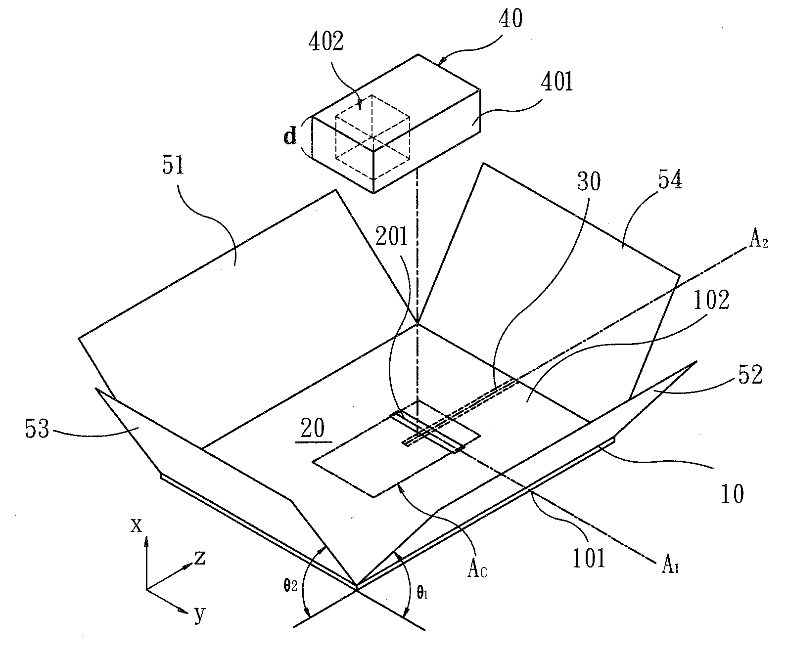
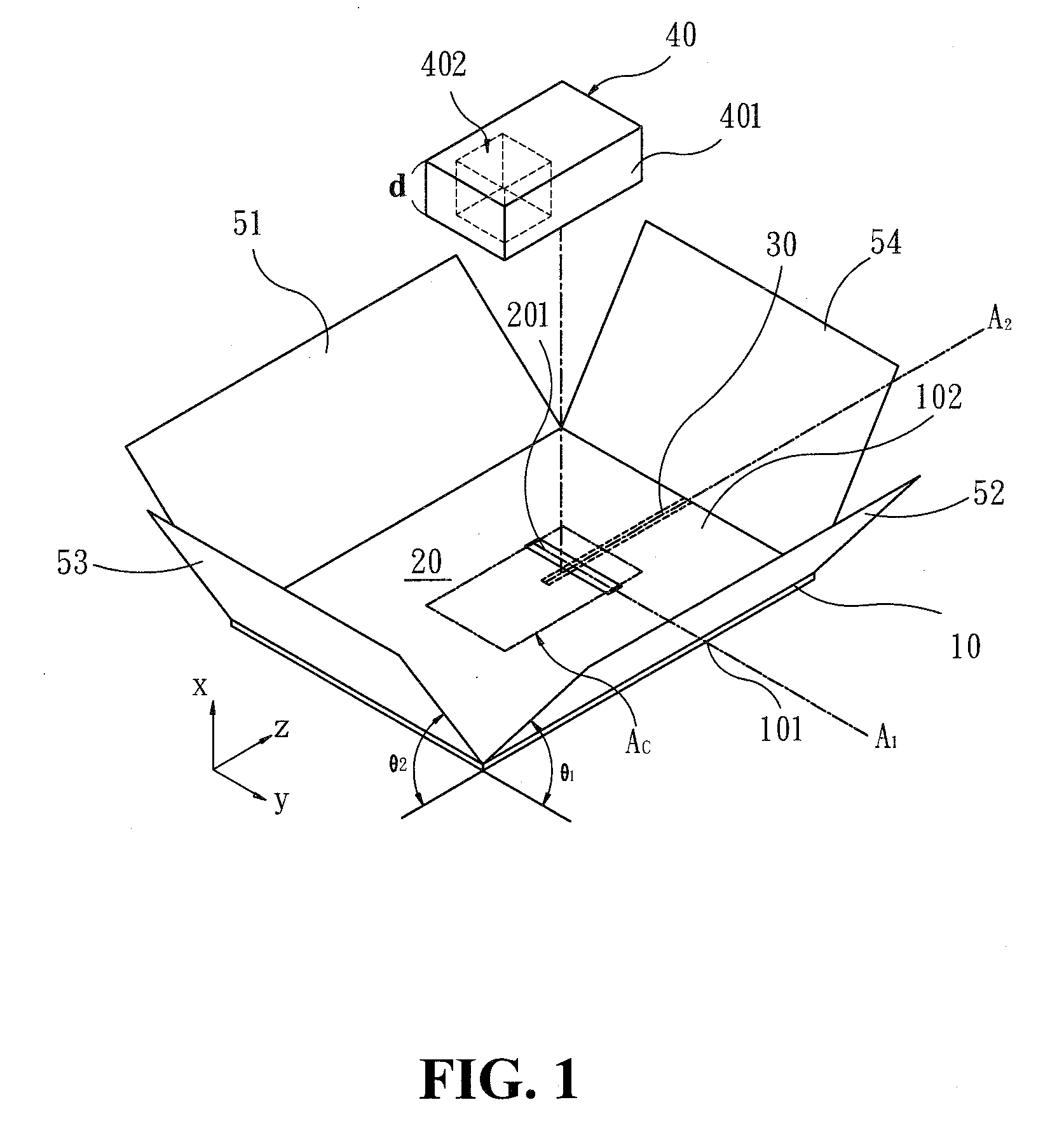
[0019]With reference to FIG. 1, illustrating the perspective view, the present invention of the DRA 1 with bending metallic planes, comprises:

[0020]a dielectric substrate 10 of plate shape including a first surface 101 and a second surface 102, which is a printed circuit board made of a material having a dielectric constant of 2-13, for example, an FR4 substrate with the dielectric constant of 4.4;

[0021]a ground plane 20 of metallic material forming on the second surface 102, and further including a rectangular hollow portion 201, of which the longer side extends along a first axis A1;

[0022]a feed conductor 30 mounted on the first surface 101, and the feed conductor 30 extends along a second axis A2 perpendicular to the first axis A1 and pass through the central part of the hollow portion 201,

[0023]a resonator 40 of dielectric material, further including a main body 401 and a caved well 402. The material of the resonator 40 provides the characteristics of high dielectric constant be...


PUM


Abstract

The present invention relates to a dielectric resonator antenna (DRA) with bending metallic planes. The ground plane of the dielectric resonator antenna is bent around the DRA to increase the half-power beam width (HPBW) and the gain on H-plane, moreover, to improve the pattern on E-plane. The ground plane of the invention is further bent in different angles to reshape the radiation pattern of the dielectric resonator antenna, and a well is carved in the dielectric resonator antenna to increase its radiation bandwidth. The invention can also be adjusted as WiMAX sectorial antenna.

Description

FIELD OF THE INVENTION[0001]The present invention is related to a dielectric resonator antenna (DRA), and more particularly, to a dielectric resonator antenna with a carved-well dielectric resonator and plurality of ground metallic planes bent in different angles.BACKGROUND OF THE INVENTION[0002]The prior rectangle DRA is usually operated in a TE111 mode, and the mode has a wide-beam linearly-polarized radiation pattern with a bandwidth of approximately 6-10% and having advantages of low loss and high radiation efficiency, and could be increased to more than 10% by using low-permittivity material with εr≦10.[0003]The beamwidth of the broadside radiation for a typical sectorial antenna is about 120°, and the half-power beamwidth (HPBW) of vertical polarization on H-plane is only about 80°, can not fulfill the requirement of the sectorial antenna.[0004]As known, the quality factor is an important parameter to affect the bandwidth. Besides, various radiation patterns can be obtained by...

Claims


Application Information

Patent Timeline
IPC IPC(8): H01Q1/48
CPCH01Q1/2291H01Q19/106H01Q13/10H01Q9/0485
Inventor CHANG, TZE-HSUANKIANG, JEAN-FU
Owner NAT TAIWAN UNIV
Why Eureka
Try Eureka