Optical disc apparatus and lens shift correction method

Inactive Publication Date: 2009-04-23
TOSHIBA SAMSUNG STORAGE TECHNOLOGY
View PDF5 Cites 3 Cited by
  • Summary
  • Abstract
  • Description
  • Claims
  • Application Information

AI Technical Summary

Benefits of technology

[0013]According to an aspect of the present invention, there is provided an optical disc apparatus which executes tracking control for an objective lens by generating a push-pull signal, comprising: a determination unit which detects symmetry of the push-pull signal and determines whether balance of signal characteristics of the push-pull signal is good; a lens shift amount detection unit which detects, in a case where the determination unit determines that

Problems solved by technology

In this case, the dynamic range of the RF amplifier cannot effectively be utilized for the signal that

Method used


Image

  • Optical disc apparatus and lens shift correction method
  • Optical disc apparatus and lens shift correction method
  • Optical disc apparatus and lens shift correction method

Examples


Embodiment Construction

[0028]An embodiment of the present invention will now be described with reference to the accompanying drawings.

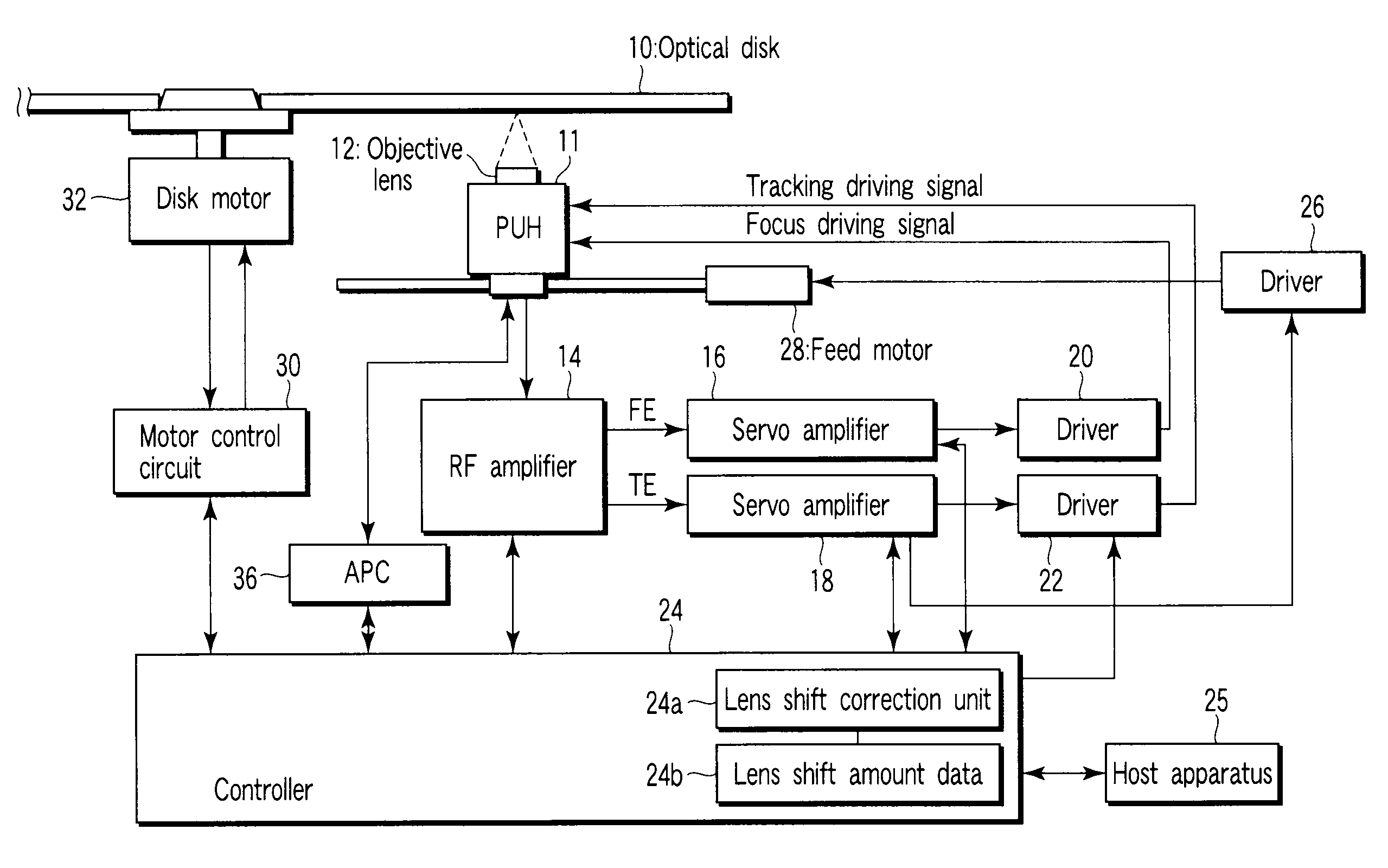
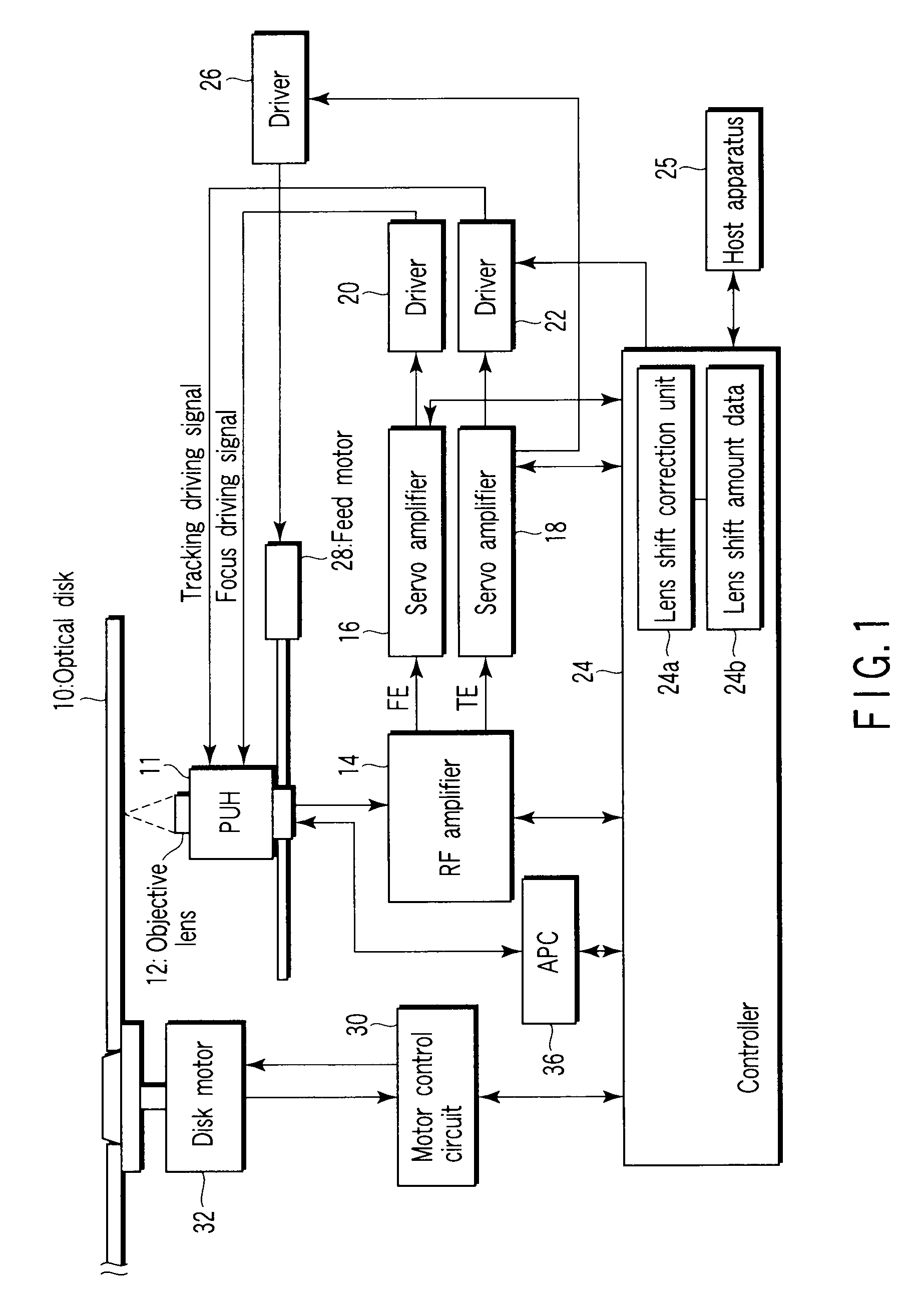
[0029]FIG. 1 is a block diagram showing the structure of an optical disc apparatus according to the embodiment.

[0030]A spiral track is formed on an optical disc 10 which serves as a recording medium. The optical disc 10 is rotated by a disc motor 32 (e.g. spindle motor) which is driven by a motor control circuit 30.

[0031]Recording / reproduction of data on / from the optical disc 10 is effected by a laser beam which is emitted from an optical pickup head (PUH) 11. The optical pickup head 11 is supported at a position facing a data read surface of the optical disc 10 in such a manner that the optical pickup head 11 is movable in a radial direction of the optical disc 10 by a feed motor 28 which is driven by a driver 26. The driver 26 is driven in accordance with a control signal which is generated by a servo amplifier 18.

[0032]The optical pickup head 11 includes a laser diode, a...


PUM


Abstract

An optical disc apparatus, which executes tracking control for an objective lens by generating a push-pull signal, includes a determination unit which detects symmetry of the push-pull signal and determines whether balance of signal characteristics of the push-pull signal is good, a lens shift amount detection unit which detects, in a case where the determination unit determines that the balance of the signal characteristics of the push-pull signal is not good, a lens shift amount of the objective lens in such a manner as to improve the balance of the signal characteristics, a memory unit which stores the lens shift amount that is detected by the lens shift amount detection unit, and an addition unit which constantly applies the lens shift amount, which is stored in the memory unit, to a tracking actuator which shifts the objective lens.

Description

CROSS-REFERENCE TO RELATED APPLICATIONS[0001]This application is based upon and claims the benefit of priority from prior Japanese Patent Application No. 2007-272870, filed Oct. 19, 2007, the entire contents of which are incorporated herein by reference.BACKGROUND OF THE INVENTION[0002]1. Field of the Invention[0003]The present invention relates to an optical disc apparatus which executes position correction of an objective lens, and a lens shift correction method.[0004]2. Description of the Related Art[0005]With development of optical disc apparatuses, models of apparatuses have been changing from a thick type (Half Height (H / H)) to a thin type (slim) to an ultra-slim type. The optical disc apparatus of the thick type (H / H) model has a thickness of, e.g. 41.5 mm. The optical disc apparatus of the thin type model has a thickness of 12.7 mm, and the optical disc apparatus of the ultra-thin type has a thickness of 9.5 mm.[0006]In general, in the optical disc apparatus, the position co...

Claims


Application Information

Patent Timeline
IPC IPC(8): G11B7/095G11B7/09
CPCG11B7/0903G11B7/0956G11B7/0953
Inventor KUROSAWA, HIDEO
Owner TOSHIBA SAMSUNG STORAGE TECHNOLOGY
Why Eureka
Try Eureka