Network Planning and Optimization of Equipment Deployment

a network and equipment technology, applied in the field of network equipment deployment analysis, can solve the problems of equipment providers losing deployment bids, difficulty in finding a properly balanced solution, and complex task of deployment of cost-effective and fault-tolerant networks, and achieve the effect of sufficient bandwidth and connectivity, and enhanced performance of nodes

Active Publication Date: 2009-04-23
INFINERA CORP
View PDF29 Cites 24 Cited by
  • Summary
  • Abstract
  • Description
  • Claims
  • Application Information

AI Technical Summary

Benefits of technology

[0010]Initial methods are performed that determine an initial number of line cards to be inserted within a chassis to support the required traffic demands of the corresponding node. A set of transport-side line cards are determined to ensure that sufficient bandwidth and connectivity is provided within a node to satisfy all transport-side demands of the deployment. A set of client-side line cards are determined to ensure that sufficient bandwidth and connectivity provided within a node to satisfy all client-side demands of the deployment. In various embodiments of the invention, the placement of these line cards may be determined to enhance the performance of the node or improve the degrees of freedom of the chassis to make a subsequent use or expansion of the chassis relatively easier.
[0011]Post-processing heuristics are applied to these sets of line cards in an attempt to reduce the amount of equipment, including line cards and chassis, deployed while still ensuring that the deployment demands are satisfied. In various embodiments of the invention, the fractional utilization on multiple line cards is analyzed to try and improve the capacity utilization of line cards within a chassis. If this line card capacity utilization is sufficiently improved, then a reduction in the amount of equipment required in the deployment of the network and greater degrees of freedom for future demands on the node may be realized.
[0012]In certain embodiments of the invention, reordering of nodal flows is performed to determine if there is a more efficient placement of line cards at a node with respect to chassis backplane connectivity and the assignment of traffic demands to those line cards in order to reduce the overall count of line cards within the network. For example, reordering of line card positions may provide a more efficient use of backplane bandwidth and would potentially reduce the number of line cards required to service traffic on the node.
[0013]In certain embodiments of the invention, client-side line card optimization is performed so to reduce the number of transport-side line cards required to service a particular number of client-side ports. This client-side line card optimization comprises reordering client-side ports to improve the utilization of transport-line cards.

Problems solved by technology

The deployment of a cost-effective and fault tolerant network can often be a complex task.
As the number of nodes or sites within a network scales, the difficulty in finding this properly balanced solution becomes increasingly complex.
An equipment provider may lose a deployment bid if its deployment proposal is too expensive (i.e., the amount of equipment deployed is more than required to satisfy the network parameters) or the equipment configuration is not able to satisfy all of the demands.
However, as the size and / or complexity of the deployment increases, this off-the-cuff judgment oftentimes fails due to the sheer magnitude of analysis required to generate the proposal.
Accordingly, an equipment manufacturer runs a risk of over-deploying equipment within a network solution to meet particular network parameters set forth by the network service provider.

Method used


Image

  • Network Planning and Optimization of Equipment Deployment
  • Network Planning and Optimization of Equipment Deployment
  • Network Planning and Optimization of Equipment Deployment

Examples


Embodiment Construction

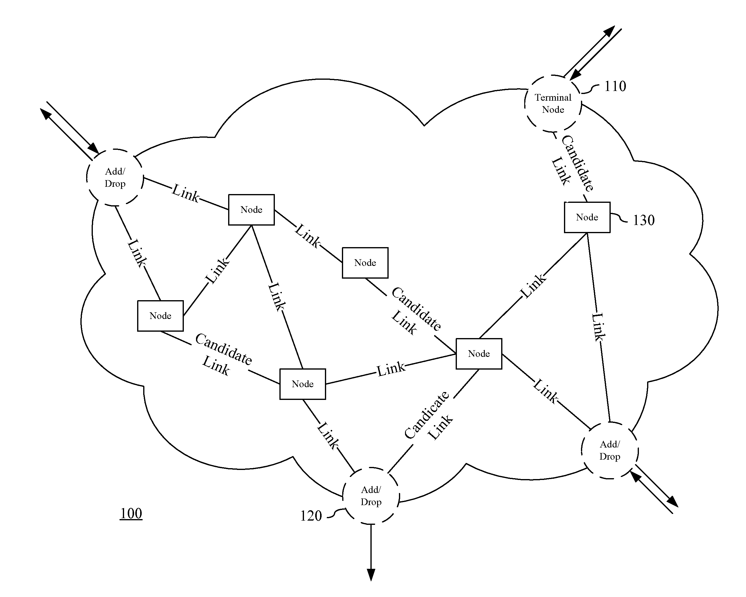
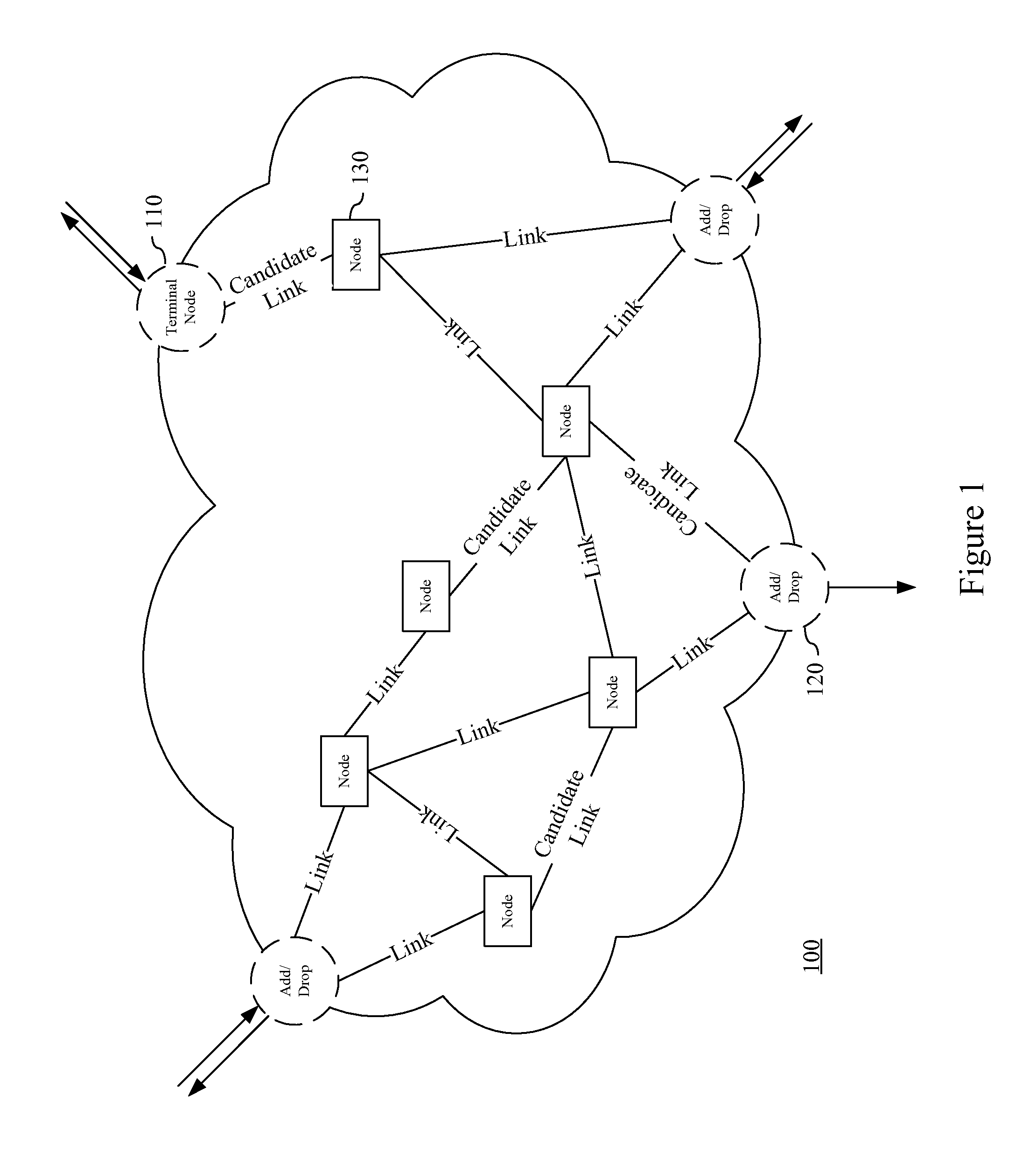
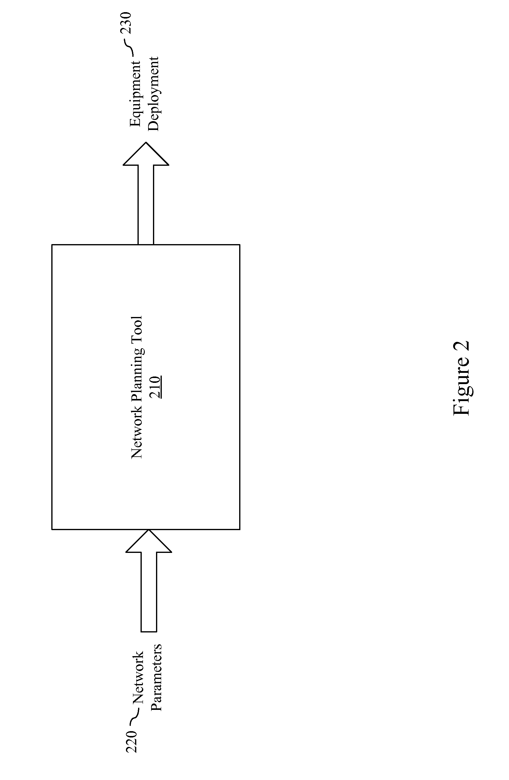
[0032]Embodiments of the present invention provide systems, devices and methods for improving the efficient deployment and configuration of networking equipment within a network build-out. In certain embodiments of the invention, an iterative analysis of inter-node equipment placement and connectivity, and inter- and intra-node traffic flow is performed to identify a preferred deployment solution. This analysis of deployment optimization takes into account both configurations from a network node perspective as well as from a network system perspective. Deployment solutions are iteratively progressed and analyzed to determine a preferred solution based on both the cost of deployment and satisfaction of the network demands. In various embodiments of the invention, a baseline marker is generated from which the accuracy of the solution may be approximated that suggests to an engineer whether the deployment has approached an optimal solution.

[0033]In the following description, for purpos...


PUM


Abstract

Embodiments of the present invention provide systems, devices and methods for improving the efficient deployment and configuration of networking equipment within a network build-out. In certain embodiments of the invention, an iterative analysis of inter-node equipment placement and connectivity, and inter- and intra-node traffic flow is performed to identify a preferred deployment solution. This analysis of deployment optimization takes into account both configurations from a network node perspective as well as from a network system perspective. Deployment solutions are iteratively progressed and analyzed to determine a preferred solution based on both the cost of deployment and satisfaction of the network demands. In various embodiments of the invention, a baseline marker is generated from which the accuracy of the solution may be approximated that suggests to an engineer whether the deployment is approaching an optimal solution.

Description

BACKGROUND[0001]A. Technical Field[0002]The present invention relates generally to the deployment of equipment within a network, and more particularly, to an analysis of network equipment deployment relative to optimization factors including intra-nodal routing and post-processing heuristics.[0003]B. Background of the Invention[0004]The deployment of a cost-effective and fault tolerant network can often be a complex task. This deployment requires that the equipment cost and network performance should be properly balanced to find an appropriate solution for a network provider. As the number of nodes or sites within a network scales, the difficulty in finding this properly balanced solution becomes increasingly complex.[0005]In building out a network, a network service provider may give an equipment manufacturer a number of different parameters and request that the manufacturer provide a cost estimate for the build-out. For example, the equipment manufacturer may be provided certain n...

Claims


Application Information

Patent Timeline
Patent Type & Authority Applications(United States)
IPC IPC(8): H04L12/28H04J14/02
CPCH04J14/0227H04J14/0278H04J14/0284H04L49/40H04L45/00H04L45/302H04L45/62H04L12/4625
Inventor HAND, STEVEN JOSEPHHANUMANTHAPPA, JAYARAMMISRA, MOHITJAIN, MANEESHVENKATESAN, RAJASEKARSAXENA, ATUL
Owner INFINERA CORP
Why Eureka
Try Eureka