
Headphones

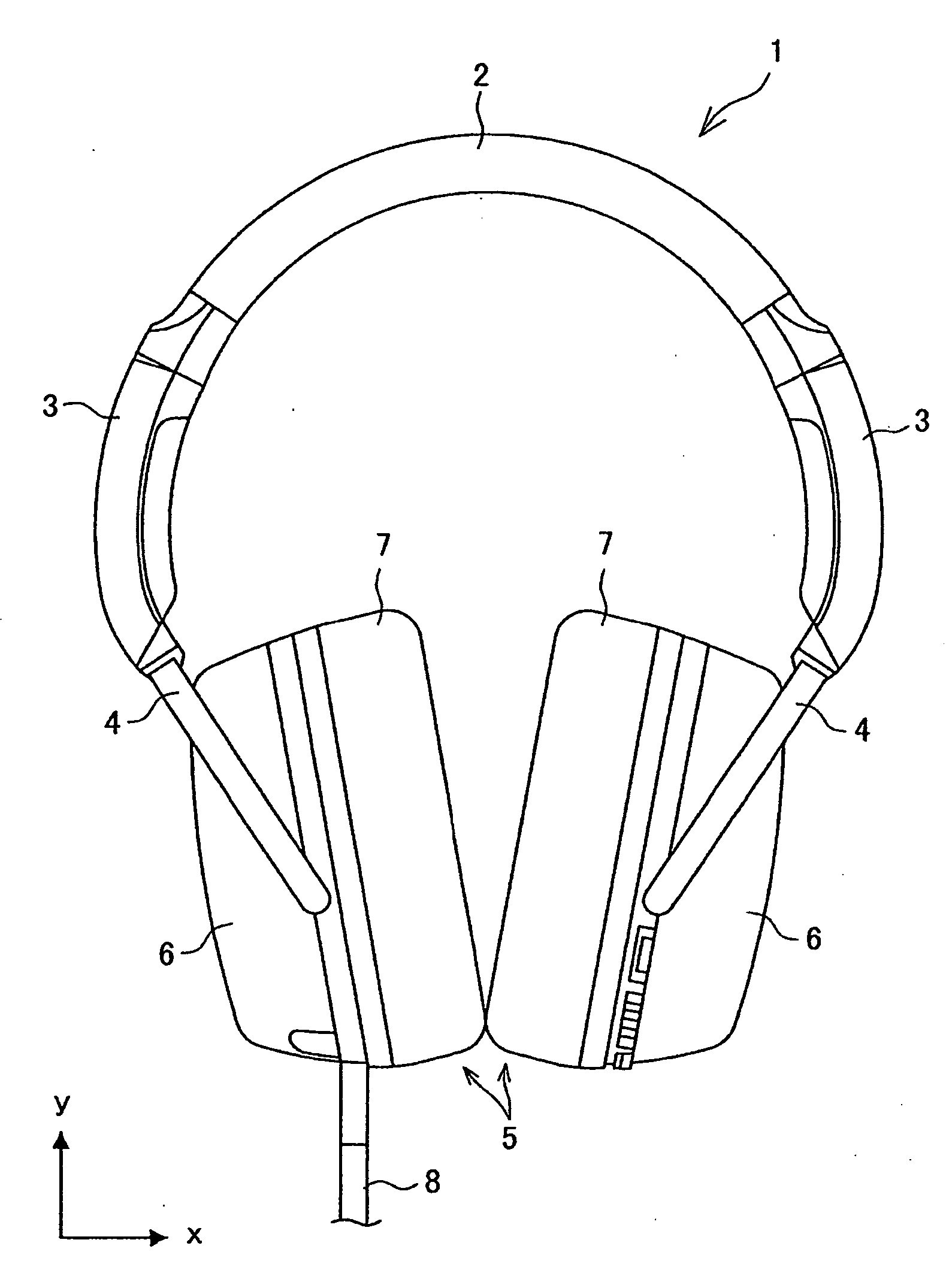
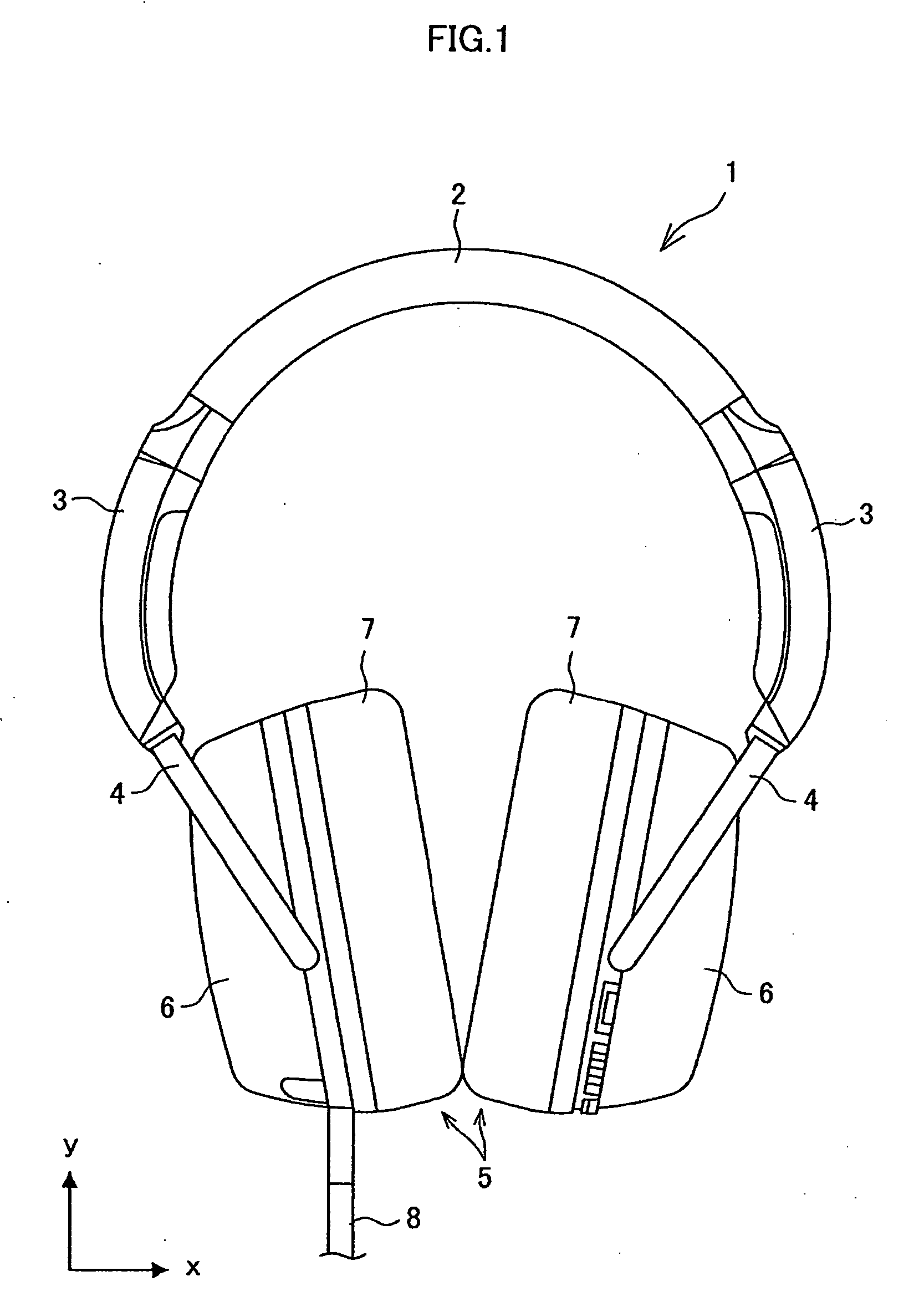
a headphone and headphone technology, applied in the field of headphones, can solve the problems of user discomfort and relationship with the position adjustment mechanism of the earcup, and achieve the effects of reducing the storage space of the cord, shortening the rotation diameter of the spiral, and improving portability

Inactive Publication Date: 2009-04-23
SONY CORP
View PDF9 Cites 34 Cited by
  • Summary
  • Abstract
  • Description
  • Claims
  • Application Information

AI Technical Summary

Benefits of technology

[0008]On the other hand, introducing the cord into either left or right earcup can reduce the above-described annoyance from the cord and discomfort of a user because the cord comes out from one housing only.
[0013]If, on the other hand, the cord is contained inside the slider mechanism, the cord is placed being bent in a space inside the slider mechanism. Thus, the cord is not exposed to the outside, and the above issues are not likely to occur. However, because the cord moves freely inside the slider mechanism, this causes issues such as an increase in the danger of a break in the cord due to a tensile or bending stress and the possibility of snagging of the cord on another member inside the slider mechanism. In order to reduce the probability of occurrence of such issues and contain the entire length of the bent cord, the slider mechanism needs to be large in size. The larger slider mechanism causes headphones to be less portable.
[0015]In light of the foregoing, it is desired to provide novel and improved headphones capable of appropriately protecting a cord and having improved portability.
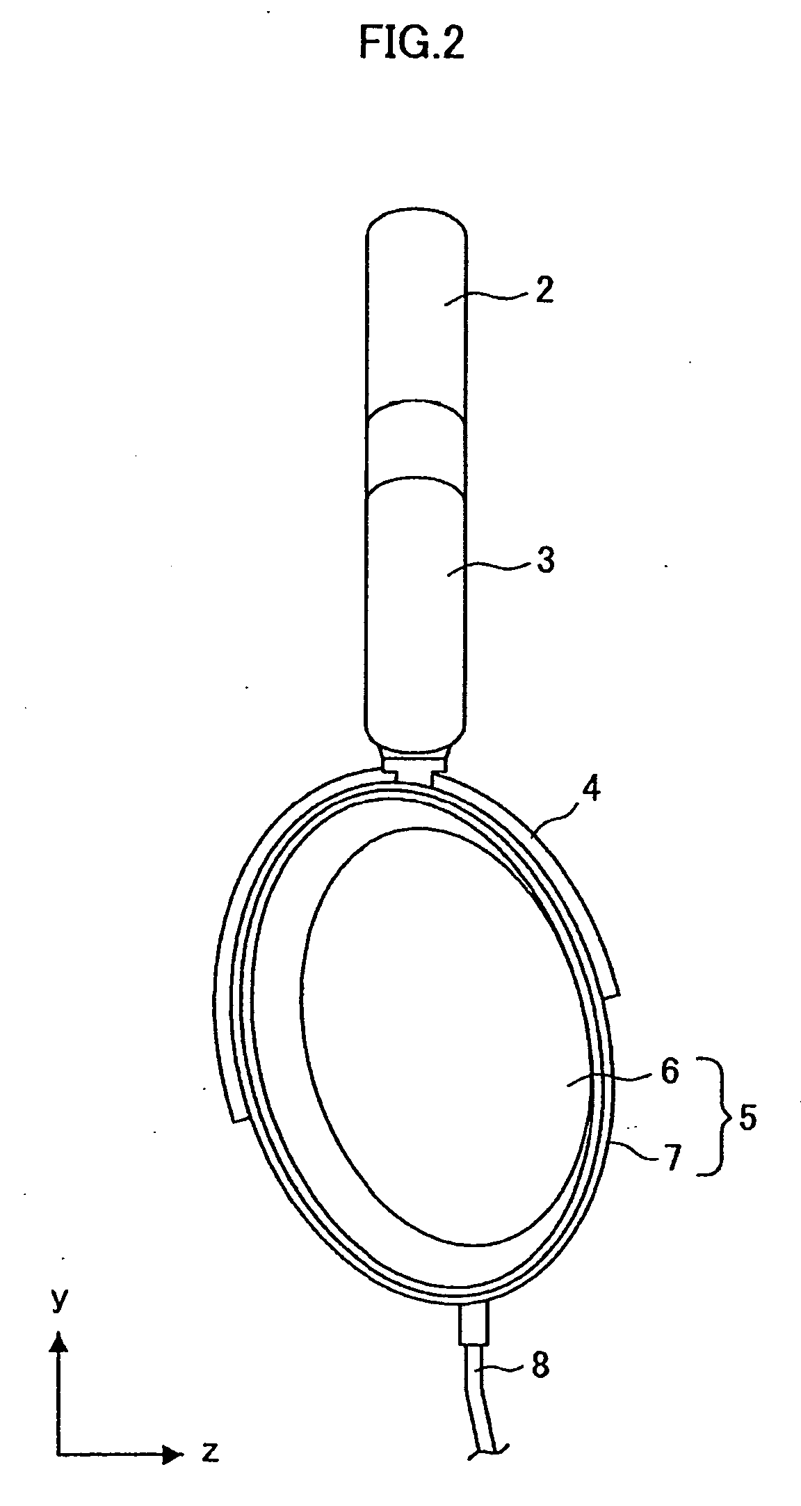
[0017]In this structure, the extension and contraction unit can be extended by drawing the small-diameter hollow member out of the large-diameter hollow member, and the extension and contraction unit can be contracted by inserting the small-diameter hollow member into the large-diameter hollow member. Accordingly, the headphones can change its shape according to the shape of the user's head by adjusting the positions of the earcups with respect to the headband. The code connecting the left and right earcups is contained in the extension and contraction unit. This prevents the cord from being exposed to the outside. Further, the cord contained in the extension and contraction unit is spirally wound, thus having elasticity (spring properties). Therefore, when the extension and contraction unit is extended or contracted, the spiral cord is extended or contracted accordingly, thereby absorbing the change in shape due to extension or contraction. This prevents the cord from being slack and moving freely inside the extension and contraction unit. Further, the cord contained in the extension and contraction unit is introduced into the extension and contraction unit via the through-holes of the nodes placed between the headband and the extension and contraction unit and between the hanger and the extension and contraction unit. The cord is thereby introduced into the extension and contraction unit substantially linearly, thus reducing the risk of snagging on another component.
[0021]The part of the cord contained in the extension and contraction unit may be wound so that a short-axis direction in a cross section of the cord corresponds to a diameter direction of a spiral. In this structure, the cord contained in the extension and contraction unit is wound so that the short-axis direction in the cross section on the plane perpendicular to the axis line direction corresponds to the diameter direction of the spiral. In other words, the cord is wound so that the long-axis direction in the cross section is substantially parallel with the rotation axis of the spiral. This shortens the rotation diameter of the spiral, thereby reducing a storage space of the cord to be secured in the extension and contraction unit.
[0022]According to the embodiments of the present invention described above, it is possible to appropriately protect a cord and improve portability.

Problems solved by technology

However, because the cord hangs down from the both earcups, the cord is an annoying nuisance when wearing or removing headphones and the cord hangs down at both sides of the user's neck while wearing headphones, which makes the user uncomfortable.
Thus, in the placement of the signal supply cord from one earcup to the other earcup, the relationship with an earcup position adjustment mechanism becomes an issue.

Method used


Image

  • Headphones
  • Headphones
  • Headphones

Examples


first embodiment

[0068]the present invention is described in the foregoing.

[0069]In the following, a second embodiment of the present invention is described with reference to FIG. 8. In the headphones according to this embodiment, the elements other than the connection cord 330 are the same as those of the headphones 1 according to the first embodiment and thus not described in detail hereinbelow.

second embodiment

[0070]FIG. 8 is an explanatory illustration showing the connection cord of the headphones according to the present invention. FIG. 8 illustrates the cross-section of a part of the connection cord as well.

[0071]A connection cord 340 is an example of a cord that supplies a signal to an acoustic circuit placed inside the housing 6 of the earcup 5, which electrically connects the left and right earcups 5. The connection cord 340 has a shape of a wide flat cable as shown in FIG. 8. Specifically, the connection cord 340 has a flat shape whose cross section on the plane intersecting with the axial line direction has the long-axis side (the side parallel with the direction P in FIG. 8) and the short-axis side (the side having the thickness d in FIG. 8). The connection cord 340 has a multi-conductor structure such as a 12-conductor cord, just like the connection cord 330 according to the first embodiment described above.

[0072]Specifically, the connection cord 340 includes 12 signal wires 333...


PUM


Abstract

There is provided headphones that include a pair of left and right earcups, an audio signal processing unit contained in the earcups, a headband connecting the left and right earcups respectively through a hanger, and a cord to supply a signal to the audio signal processing unit. In the headphones, a connection portion between the hanger and the headband is configured as an extension and contraction unit having a multistage structure including a small-diameter hollow member able to be taken in and out of a large-diameter hollow member, a part of the cord contained in the extension and contraction unit is spirally wound so as to be extended and contracted, nodes are placed respectively between the headband and the extension and contraction unit and between the hanger and the extension and contraction unit, and the respective nodes have a through-hole allowing penetration of the cord.

Description

CROSS REFERENCES TO RELATED APPLICATIONS[0001]The present invention contains subject matter related to Japanese Patent Application JP 2007-274000 filed in the Japan Patent Office on Oct. 22, 2007, the entire contents of which being incorporated herein by reference.BACKGROUND OF THE INVENTION[0002]1. Field of the Invention[0003]The present invention relates to headphones.[0004]2. Description of the Related Art[0005]Headphones are used for a user wearing them to listen to sounds. Headphones have two (left and right) earcups each containing a loudspeaker. The both earcups are connected by a headband.[0006]In order to drive the loudspeakers or the like of the headphones, it is necessary to provide an audio signal into the left and right earcups. As a wiring for supplying an audio signal, a distribution cord from an external connection terminal may be introduced into both of the left and right earcups, or it may be introduced into either one of the left and right earcups.SUMMARY OF THE I...

Claims


Application Information

Patent Timeline
Patent Type & Authority Applications(United States)
IPC IPC(8): H04R25/00H04R1/10
CPCH04R2460/01H04R5/0335
Inventor ISHIDA, HIROYUKITSUNODA, NAOTAKA
Owner SONY CORP
Learn More