Controlled centrifuge systems

a centrifuge and control technology, applied in the field of centrifuges, can solve the problems of large physical size of the centrifuge, problems that can occur, and the amount of energy required to process the mixtur

Active Publication Date: 2009-04-23
NAT OILWELL VARCO LP
View PDF98 Cites 92 Cited by
  • Summary
  • Abstract
  • Description
  • Claims
  • Application Information

AI Technical Summary

Benefits of technology

[0012]The present invention discloses, in certain aspects, methods for controlling a centrifuge system, the centrifuge system including: a bowl; a bowl motor system for rotating the bowl, rotation of the bowl resulting in a G-force applied to the bowl; a bowl variable frequency drive for driving the bowl motor; a conveyor rotatable within the bowl; a conveyor motor for rotating the conveyor; a conveyor variable frequency drive for driving the conveyor motor; a pump for pumping material to be centrifuged in the bowl; a pump motor for driving the pump; a pump variable frequency drive for driving the pump motor; a control system for controlling the bowl variable frequency drive, the conveyor variable frequency drive, and the pump variable frequency drive, the control system i

Problems solved by technology

To accommodate such feed rates, high torques are encountered, much energy is required to process the mixture, and the physical size of the centrifuge can become enormous.
Problems can occur if the centrifuge's differential gearbox overheats or is damaged from too-high gearbox speed differentials.
Gearbox damage and overheating can occur when the backdrive motor is operated in forward or in reverse.
Centrifuge manufacturers often specify gearbox differential speeds that must

Method used


Image

  • Controlled centrifuge systems
  • Controlled centrifuge systems
  • Controlled centrifuge systems

Examples


Embodiment Construction

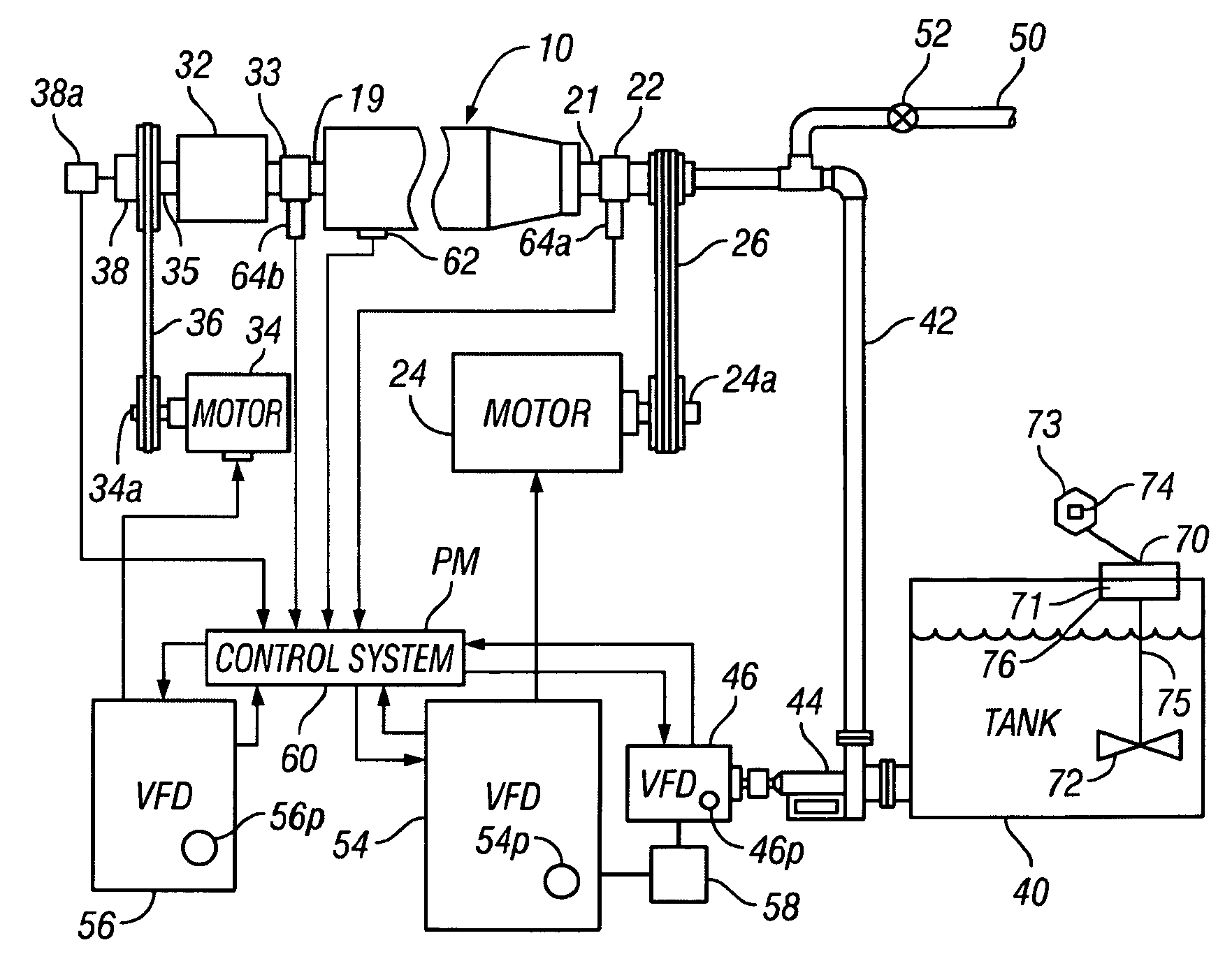
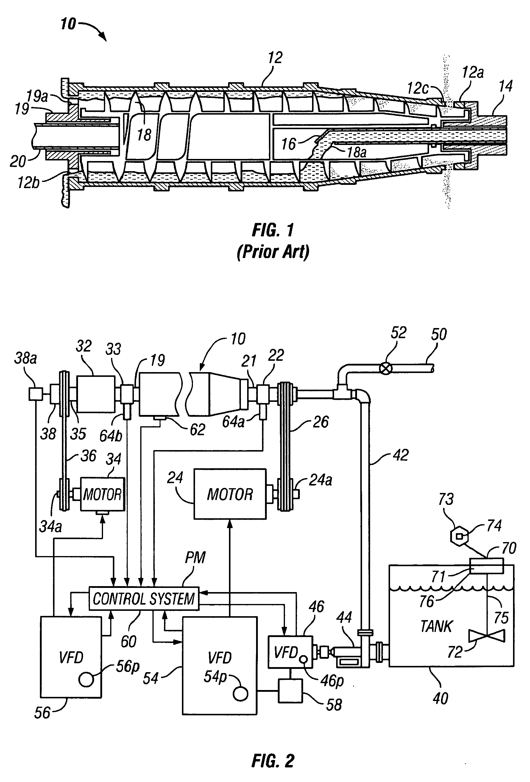
[0104]As shown in FIGS. 1 and 2, a centrifuge system 10 according to the present invention has a bowl 12, supported for rotation about its longitudinal axis, has two open ends 12a and 12b, with the open end 12a receiving a drive flange 14 which is connected to a drive shaft for rotating the bowl. The drive flange 14 has a longitudinal passage which receives a feed tube 16 for introducing a feed slurry, e.g. drilling material, into the interior of the bowl 12. A screw conveyor 18 extends within the bowl 12 in a coaxial relationship thereto and is supported for rotation within the bowl. A hollow flanged shaft 19 is disposed in the end 12b of the bowl and receives a drive shaft 20 of an external planetary gear box for rotating the screw conveyor 18 in the same direction as the bowl at a selected speed.

[0105]The wall of the conveyor 18 has one or more openings 18a near the outlet end of the tube 16 so that the centrifugal forces generated by the rotating bowl 12 move the slurry radially...


PUM

PropertyMeasurementUnit
Fractionaaaaaaaaaa
Fractionaaaaaaaaaa
Fractionaaaaaaaaaa

Abstract

Centrifuge systems and methods for controlling centrifuge systems, the systems in certain aspects for processing material, e.g., but not limited to drilling fluids with solids therein. This abstract is provided to comply with the rules requiring an abstract which will allow a searcher or other reader to quickly ascertain the subject matter of the technical disclosure and is submitted with the understanding that it will not be used to interpret or limit the scope or meaning of the claims, 37 C.F.R. 1.72(b).

Description

CROSS-REFERENCE TO RELATED APPLICATIONS[0001]This is: a continuation-in-part of U.S. application Ser. No. 11 / 253,067 filed Oct. 18, 2005; a continuation-in-part of U.S. application Ser. No. 11 / 096,192 filed Mar. 31, 2005; a continuation-in-part of U.S. application Ser. No. 10 / 949,882 filed Sep. 25, 2004; a continuation-in-part of U.S. application Ser. No. 10 / 835,256 filed Apr. 29, 2004; a continuation-in-part of U.S. Ser. No. 10 / 512,372 filed Oct. 25, 2004 which claims priority from U.S. Ser. No. 10 / 134,027 filed Apr. 26, 2002 and Application Ser. No. PCT / IB03 / 01031 filed Mar. 12, 2003; and a continuation-in-part of U.S. Ser. No. 10 / 373,216 filed Feb. 24, 2003 which claims priority from U.S. Application Ser. No. 60 / 424,262 filed Nov. 6, 2002—all of which are incorporated fully herein and with respect to all of which the present invention claims priority under the Patent Laws.BACKGROUND OF THE INVENTION[0002]1. Field of the Invention[0003]This invention relates generally to centrifug...

Claims


Application Information

Patent Timeline
IPC IPC(8): B04B9/10B04B13/00
CPCB04B1/2016B04B1/20
Inventor DORRY, KHALED ELSMITH, GEORGE EDWARDGUGGARI, MALLAPPA ISHWARAPPAKOEDERITZ, WILLIAM L.
Owner NAT OILWELL VARCO LP
Why Eureka
Try Eureka