Vena Cava Filter with Stent

a filter and vena cava technology, applied in the field of vena cava filter with stent, can solve the problems of stent-filter units being believed not to be retrievable, serious complications and even death, pe,

Inactive Publication Date: 2009-04-23
CR BARD INC
View PDF21 Cites 156 Cited by
  • Summary
  • Abstract
  • Description
  • Claims
  • Application Information

AI Technical Summary

Benefits of technology

[0007]Accordingly, implantable medical devices including one or more filters and a stent are described herein. In one embodiment, an implantable medical device includes a radially expandable structure, having an open proximal end and an open distal end, and a plurality of filaments attached to the structure proximate at least one of the ends, the filaments being connected together to define a first filtering element. In another embodiment, an implantable medical device includes a filter including a plurality of legs joined at a proximal end to a hub, a radially expandable structure, having an open proximal end and an open distal end, and a plurality of filaments attaching the filter to the structure. In yet another embodiment, an implantable medical device includes a radially expandable structure, having an open proximal end and an open distal end defining a longitudinal axis extending therethrough, and a filter including a plurality of appendages disposed partly inside the radially expandable structure and joined at a proximal end to a hub.

Problems solved by technology

Inferior vena cava (IVC) filters are devices configured for insertion into a blood vessel to capture particles that may be present in the blood stream which, if transported to, for example, the lungs could result in serious complications and even death.
When a thrombus clot loosens from the site of formation and travels to the lung, it may cause PE, a life-threatening condition.
However, these stent-filter units are believed not to be retrievable after implantation into a blood vessel.

Method used


Image

  • Vena Cava Filter with Stent
  • Vena Cava Filter with Stent
  • Vena Cava Filter with Stent

Examples


Embodiment Construction

in conjunction with the accompanying drawings that are first briefly described.

BRIEF DESCRIPTION OF THE DRAWINGS

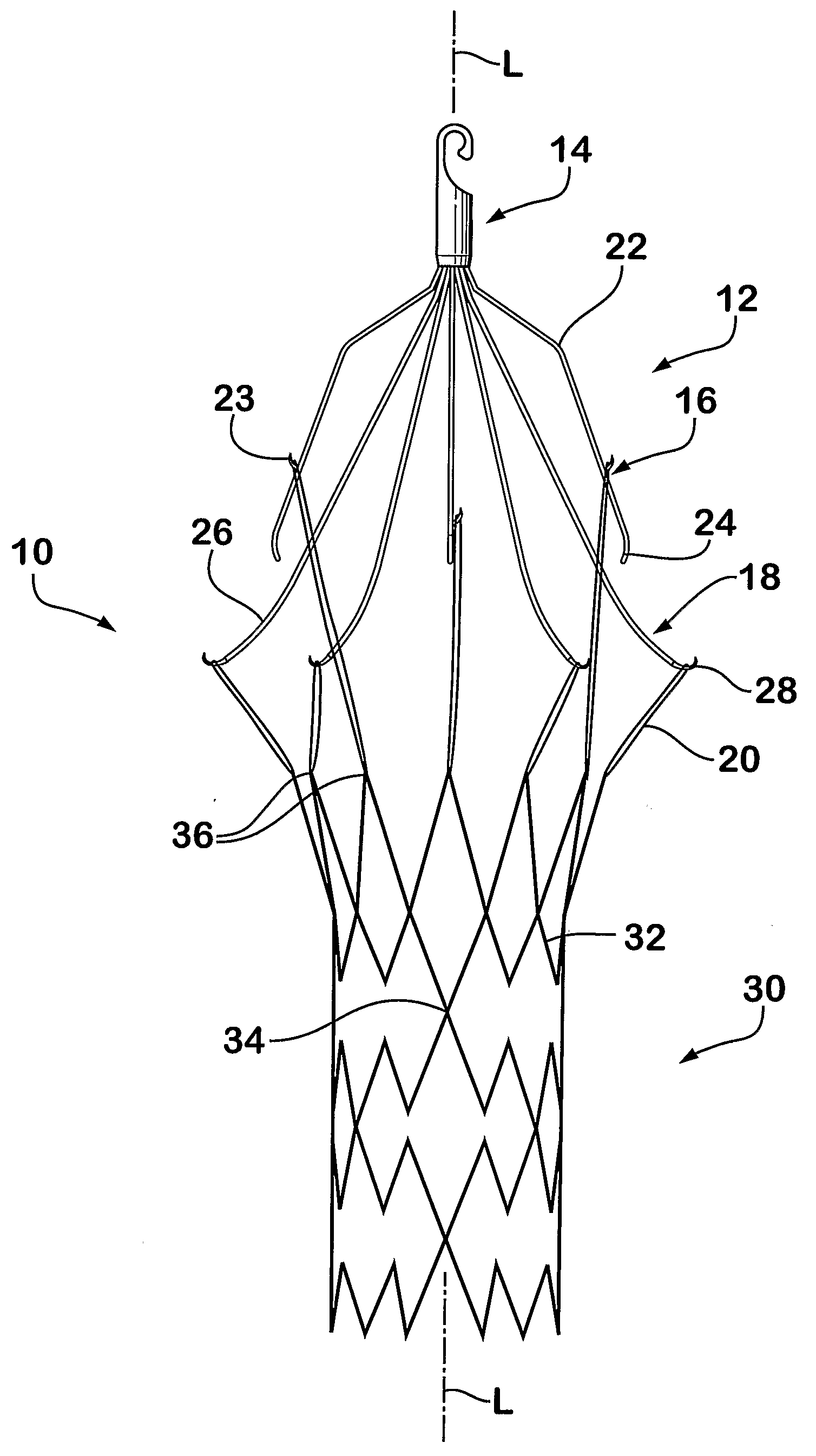
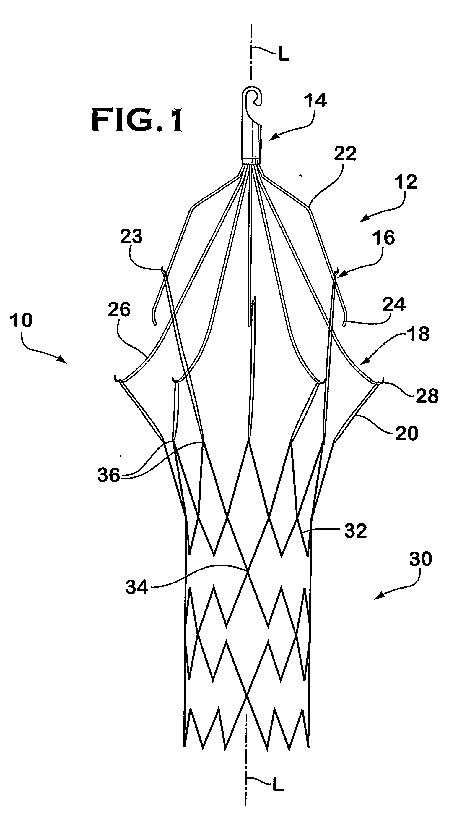
[0010]FIG. 1 is a side view of one embodiment of an implantable medical device including a filter and a stent.

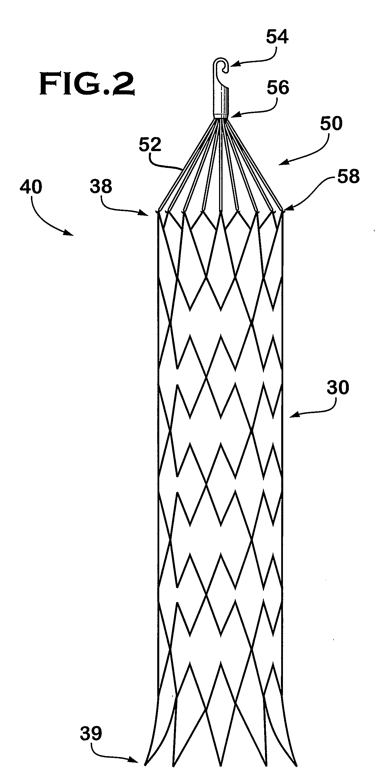
[0011]FIG. 2 is a side view of another embodiment of an implantable medical device, including a filtering element and a stent.

[0012]FIG. 3 is a side view with a partial cut-away portion of another embodiment of an implantable medical device, including a first and second filtering element and a stent.

[0013]FIG. 4 is a side view with a partial cut-away portion of another embodiment of an implantable medical device including a filter and a stent.

[0014]FIG. 5 is a side view of one embodiment of a filter with a centralized hub.

DETAILED DESCRIPTION OF THE PREFERRED EMBODIMENTS

[0015]The following detailed description should be read with reference to the drawings, in which like elements in different drawings are identically numbered. The drawings, which are not necessarily...


PUM


Abstract

An implantable medical device is described, including a filtering element and radially expandable structure. In one variation, the filtering element may include a pluralit of filaments attached to the structure, the filaments being joined together at a proximal en thereof. The filtering element may include strut members and a hub attached to the proxima end of the filaments. The filaments may be made of suture material. In another variation, the filtering element may include a filter with a plurality of legs, the filter being attached to the support structure via a plurality of filaments.

Description

PRIORITY[0001]This application claims the benefit of priority to U.S. Application No. 60 / 748,237, filed Dec. 7, 2005, which is incorporated by reference into this application as if fully set forth herein.BACKGROUND[0002]Inferior vena cava (IVC) filters are devices configured for insertion into a blood vessel to capture particles that may be present in the blood stream which, if transported to, for example, the lungs could result in serious complications and even death. Typically, IVC filters are utilized in patients who have a contraindication to anticoagulation or in patients developing clinically apparent deep vein thrombosis (DVT) and / or pulmonary embolism (PE). Patients who have recently suffered from trauma, have experienced a heart attack (myocardial infarction), or who have undergone major surgical procedure (e.g., surgical repair of a fractured hip, etc.) may develop clinically apparent DVT. When a thrombus clot loosens from the site of formation and travels to the lung, it ...

Claims


Application Information

Patent Timeline
Patent Type & Authority Applications(United States)
IPC IPC(8): A61M29/00A61F2/06A61F2/90
CPCA61F2/01A61F2/852A61F2/90A61F2250/0063A61F2002/016A61F2230/0006A61F2230/0054A61F2230/0067A61F2230/0069A61F2230/0078A61F2230/008A61F2220/0008A61F2230/005
Inventor CHANDUSZKO, ANDRZEJ J.SMALE, JOSHUA A.
Owner CR BARD INC
Why Eureka
Try Eureka