
Image forming apparatus and job information management method

Inactive Publication Date: 2009-04-23
KONICA MINOLTA BUSINESS TECH INC
View PDF3 Cites 2 Cited by
  • Summary
  • Abstract
  • Description
  • Claims
  • Application Information

AI Technical Summary

Benefits of technology

[0009]The present invention is achieved in view of above problems, and an object of the present invention is to prevent operation speeds of reading and writing the job information from slowing down and to store the large amount of the job information so as to improve a function of managing the job information.

Problems solved by technology

Thus, the image forming apparatus of Japanese Patent Application Laid-Open Publication No. 2004-178325 has an unstable function because a speed of communication between the image forming apparatus and the memory to store the job information possibly slows down.
Moreover, according to Japanese Patent Application Laid-Open Publication No. 2004-178325, even when the job information is stored in the memory inside the image forming apparatus, not in the external apparatus, since there is a limit of memory capacity, the image forming apparatus has problems that the job information is deleted in order from the oldest one, and that if the memory is a volatile memory, the job information stored in the memory disappear when a power is turned off.
Furthermore, according to Japanese Patent Application Laid-Open Publication No. 2004-178325, even when the job information of the completely executed job is stored in a nonvolatility memory (for example, an HDD and the like), since there is also a limit of memory capacity in the nonvolatility memory, a problem that the memory is occupied occurs.

Method used


Image

  • Image forming apparatus and job information management method
  • Image forming apparatus and job information management method
  • Image forming apparatus and job information management method

Examples


first embodiment

[0022]An embodiment of the present invention will be described in detail with reference to drawings below.

[0023]Firstly, a configuration will be explained.

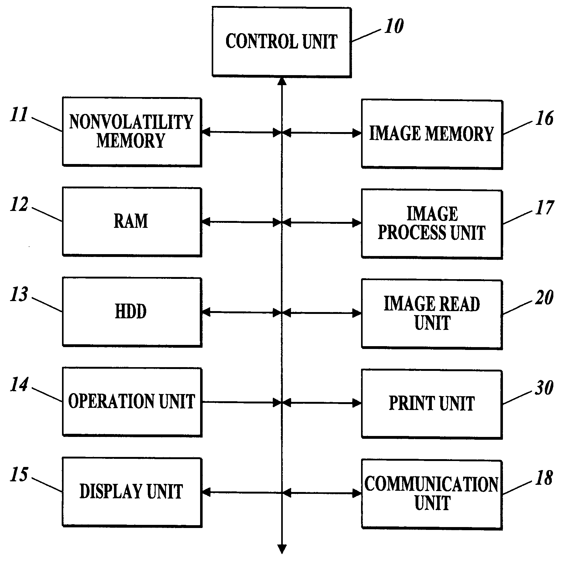
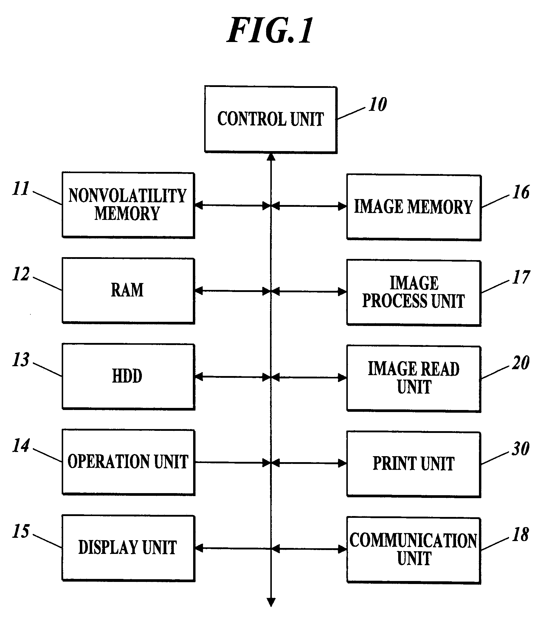
[0024]FIG. 1 is a configuration drawing of an image forming apparatus according to the first embodiment.

[0025]As shown in FIG. 1, the image forming apparatus includes a control unit 10, a nonvolatility memory 11, a Random Access Memory (RAM) 12, a Hard Disk Drive (HDD), an operation unit 14, a display unit 15, an image memory 16, an image process unit 17, a communication unit 18, an image read unit 20, a print unit 30 and the like, and these units are electrically connected to one another.

[0026]The control unit 10 includes a Central Processing Unit (CPU) and the like, and expands a system program, various control programs and various pieces of data, which are stored in the nonvolatility memory 11, into the RAM 12 to collectively control each unit of the image forming apparatus in cooperation with these programs and data.

[0027]More...

second embodiment

[0092]The second embodiment of the present invention will be described in detail with reference to the drawings below.

[0093]Since a configuration drawing of the image forming apparatus according to the second embodiment is almost same as the configuration drawing of the image forming apparatus according to the first embodiment shown in FIG. 1, an illustration thereof is omitted, and only differences between the configurations will be explained.

[0094]The control unit 10 according to the second embodiment has a timer function as a time-keeping section to keep a time and date. Moreover, the control unit 10 executes a job history data storing processing and a job history data displaying processing to realize a function as a control section to manage the job history data. In the job history data storing processing, job information (job history data) of a completely executed job is stored into a RAM 12 and the HDD 13. In the job history data displaying processing, the job history data is ...


PUM


Abstract

Disclosed an image forming apparatus including: a first storage section to store job information of a completely executed job; a nonvolatile second storage section to store the job information, the second storage section being larger in capacity than the first storage section; and a control section to compress the job information to store the compressed job information into the second storage section, and to manage the job information.

Description

BACKGROUND[0001]1. Field of the Invention[0002]The present invention relates to an image forming apparatus and a job information management method.[0003]2. Description of Related Art[0004]In recent years, there has been known an image forming apparatus such as a printer, a scanner, a facsimile, a copier, and a multi function peripheral (MFP) having various functions such as an image forming function, a copying function, a scanner function, and a facsimile function.[0005]The image forming apparatus manages information (hereinafter referred to job information) of a job to be executed by the image forming apparatus with the aim of storing the job information of a completely executed job into a memory, counting the pieces of the job information according to user's intended purpose or a predetermined item, and displaying a counting result or a history of the job information.[0006]For example, Japanese Patent Application Laid-Open Publication No. 2004-178325 discloses a job account server...

Claims


Application Information

Patent Timeline
IPC IPC(8): G06F7/00G06F1/26G06F17/30
CPCH04N1/32122H04N2201/0094H04N2201/3202H04N2201/3212H04N2201/3214H04N2201/3274H04N2201/3216H04N2201/3219H04N2201/3221H04N2201/3223H04N2201/3215
Inventor KITA, KOJI
Owner KONICA MINOLTA BUSINESS TECH INC
Learn More