Self-inflating tire valve

a self-inflating, tire valve technology, applied in the direction of tire measurement, vehicle components, transportation and packaging, etc., can solve the problems of under-inflating tires, not regularly checking air pressure, and slow leakage of inflation air in pneumatic tires, so as to reduce fuel consumption, improve driving safety, and reduce tire wear

Inactive Publication Date: 2009-04-30
KABAKOV VLADIMIR M
View PDF8 Cites 18 Cited by
  • Summary
  • Abstract
  • Description
  • Claims
  • Application Information

AI Technical Summary

Benefits of technology

[0013]The principal objects of the present invention is to reduce fuel consumption, tire wearing and to improve driving safety of a vehicle by keeping the tires fully inflated at a correct pressure at all times without requiring the user's attention. This has to be achieved by using a new type of tire valves which are not only used for inflating the tire from the external sources and for preventing air escaping from the tire, but also keep the tires properly inflated during the vehicle's operation.

Problems solved by technology

However, pneumatic tires can be subject to slow leaks of inflation air.
Hence, operators often tend not to checking air pressure regularly.
As a result, the under-inflation of tires is considered the most common car problem today.
Tire pressure directly impacts fuel efficiency.
Under-inflated tires have a higher rolling resistance, this results in increased fuel consumption.
The under-inflation of tires also impairs steerability and degrades driving safety.
Furthermore, the reduced footprint results in additional wear of the tires.
Unfortunately, such devices have a limited practical usage.
Any additional openings in the vehicle's rim with the valves that are supposed to be used not only for preventing the air escaping from the tire but also for pumping the air into the tire can reduce the reliability of the system.
Furthermore, most of the prior art air pumping systems are too complex to be workable.

Method used


Image

  • Self-inflating tire valve
  • Self-inflating tire valve
  • Self-inflating tire valve

Examples


Embodiment Construction

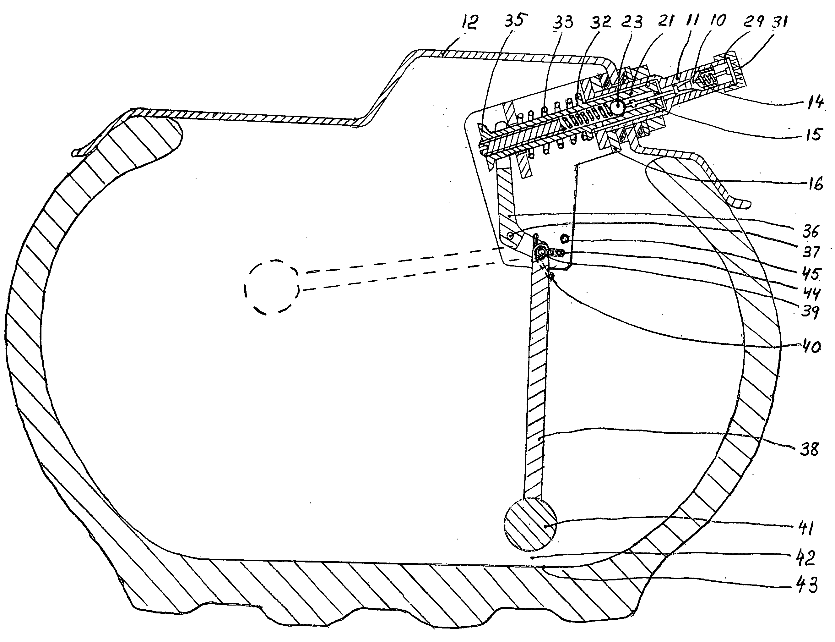
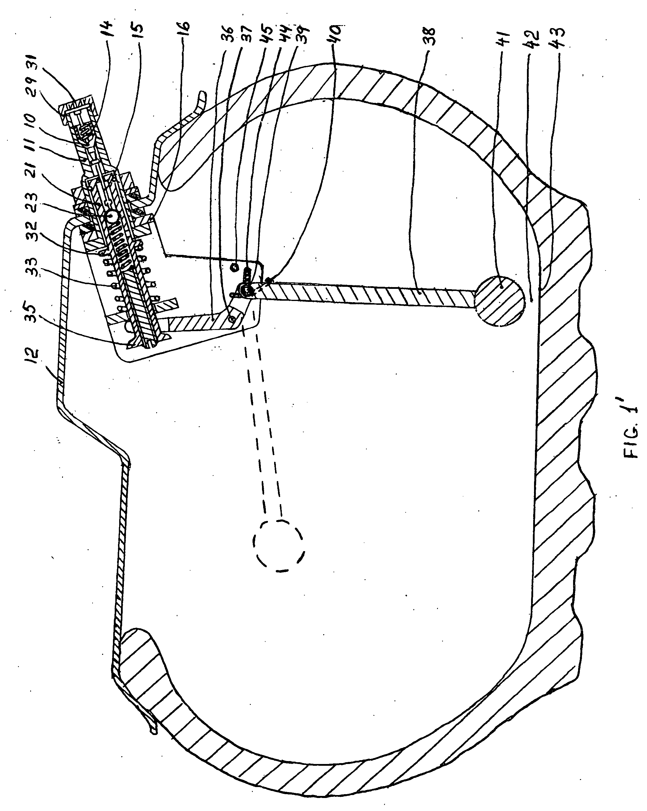
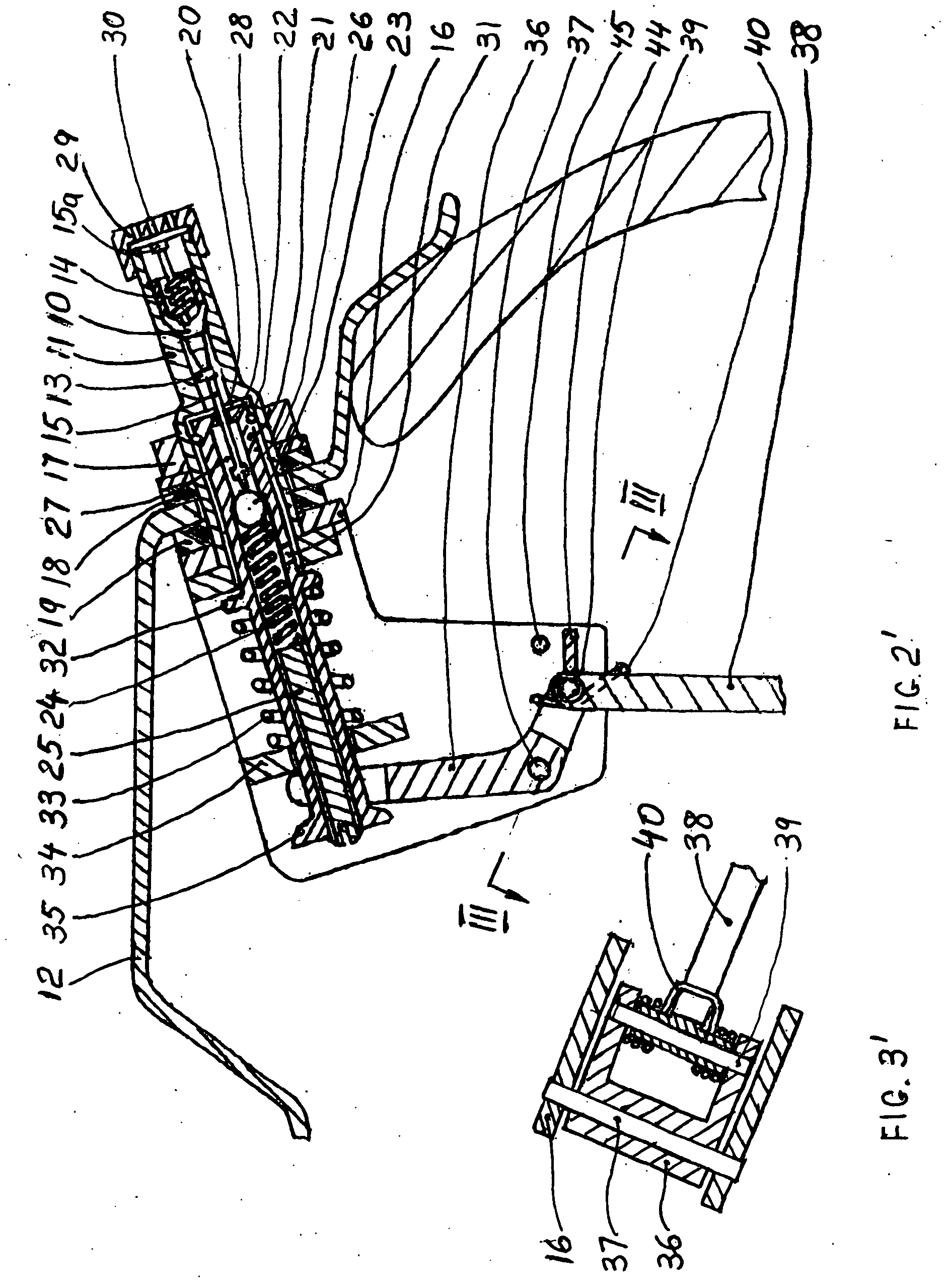
[0026]A tire valve incorporated with the pumping device for automatically maintaining the tire inflation in a vehicle's wheels will become apparent from the following description taken in conjunction with presently preferred embodiment thereof with reference to the accompanying drawings. The identical details in all the drawings have the same designations.

[0027]Turning to FIGS. 1′-4′, the preferred embodiment of the invented tire valve includes a conventional valve core 10, such as a Schruder type, disposed within a valve stem 11 which is mounted on the wheel rim 12. The valve core 10 includes a seal 13, a spring 14 and a valve actuator 15. The outer end 15a of the actuator is supposed to be pressed by a consumer to open the tire valve for inflating the tire from an external source (not shown). The tire valve is fixed to the wheel's rim 12 together with a bracket 16 by a nut 17 through the sealing rings 18 and 19.

[0028]The valve stem 11 is provided with a cylindrical bore 20 wherein...


PUM


Abstract

Small air pumping devices are mounted directly in the conventional tire valves to keep the vehicle's tires properly inflated without requiring the user's attention. If a tire is beginning to become under-inflated, a pumping piston having a single check valve is moved reciprocally in the tire valve stem by the cyclical deformation of the tire during the vehicle's travelling. The ambient air is pumped into the tires through the tire valves. The tire valves incorporating the pumping devices are kept using in a regular manner for reliably preventing air escaping from the tires and for inflating the tires from the external sources. Such “self-inflating” tire valves may be mounted as the regular tire valves both in new manufactured vehicles or in used vehicles without any modifications in the vehicle's axes, wheels or tires and without the necessity to make additional openings in the wheel.

Description

BACKGROUND OF THE INVENTION[0001]1. Cross-Reference to Related Applications[0002]The present application is a continuation-in-part of application Ser. No. 11 / 979076 filed on Oct. 31, 2007 which is now copending.[0003]2. Field of the Invention[0004]This invention relates to methods and apparatus for keeping a vehicle's tires properly inflated, and more particularly, it pertains to a tire valve including a pumping device which maintains the tire properly inflated by automatically pumping small amounts of ambient air when the tire beginning to become under-inflated.[0005]3. Technical Background[0006]Vehicle's tires are designed to be used at the air pressure specified by the manufactures to optimize the performance and fuel economy, to maximize tire life, and for driving safety.[0007]However, pneumatic tires can be subject to slow leaks of inflation air. Because of various “natural” sources of leaks, such as permeability of the tire material, not hermetical joints between the tire and ...

Claims


Application Information

Patent Timeline
Patent Type & Authority Applications(United States)
IPC IPC(8): B60C23/00
CPCB60C23/12B60C23/126B60C23/135
Inventor KABAKOV, VLADIMIR M.
Owner KABAKOV VLADIMIR M
Why Eureka
Try Eureka