System and method for avoiding contact stiction in micro-electromechanical system based switch

a micro-electromechanical and switch technology, applied in the field of electric circuitry, can solve the problems of large circuit breakers, circuit breakers that are bulky and electromechanical switches, and the switch of these circuit breakers generally operates at relatively slow speeds

Active Publication Date: 2009-04-30
GENERAL ELECTRIC CO
View PDF21 Cites 4 Cited by
  • Summary
  • Abstract
  • Description
  • Claims
  • Application Information

AI Technical Summary

Benefits of technology

[0006]Generally, aspects of the present invention provide a system that includes micro-electromechanical system switching circuitry, such as may be made up of a plurality of micro-electromechanical switches. The plurality of micro-electromechanical switches may generally operate in a closed switching condition during system operation. A controller is coupled to the electromechanical switching circuitry. The controller may be configured to actuate at least one of the micro-electromechanical switches to a temporary open switching condition while a remainder of micro-electromechanical switches remains in the closed switching condition to conduct a load current and avoid interrupting system operation. The temporary open switching condition of the switch is useful to avoid a tendency of switch contacts to stick to one another.

Problems solved by technology

Traditionally, most conventional circuit breakers include bulky electromechanical switches.
Unfortunately, these conventional circuit breakers are large in size thereby necessitating use of a large force to activate the switching mechanism.
Additionally, the switches of these circuit breakers generally operate at relatively slow speeds.
Furthermore, these circuit breakers are disadvantageously complex to build and thus expensive to fabricate.
Moreover, energy associated with the arc may seriously damage the contacts and / or present a burn hazard to personnel.
However, since solid-state switches do not create a physical gap between contacts when they are switched into a non-conducting state, they experience leakage current.
Furthermore, due to internal resistances, when solid-state switches operate in a conducting state, they experience a voltage drop.
Both the voltage drop and leakage current contribute to the dissipation of excess power under normal operating circumstances, which may be detrimental to switch performance and life.
It has been observed, however, that MEMS switching devices can exhibit contact stiction or a tendency of contacts of the switch to stick to one another (e.g., the switch contacts can remain closed when commanded to open, or can exhibit an unacceptable time delay in opening when commanded to open) after having been closed for a relatively long period of time, which may vary depending on the characteristics of a given switch.
This can lead to degraded performance when the switching device takes longer to open than a specified switching time, and can even lead to a failure when the switch fails to open at all.

Method used


Image

  • System and method for avoiding contact stiction in micro-electromechanical system based switch
  • System and method for avoiding contact stiction in micro-electromechanical system based switch
  • System and method for avoiding contact stiction in micro-electromechanical system based switch

Examples


Embodiment Construction

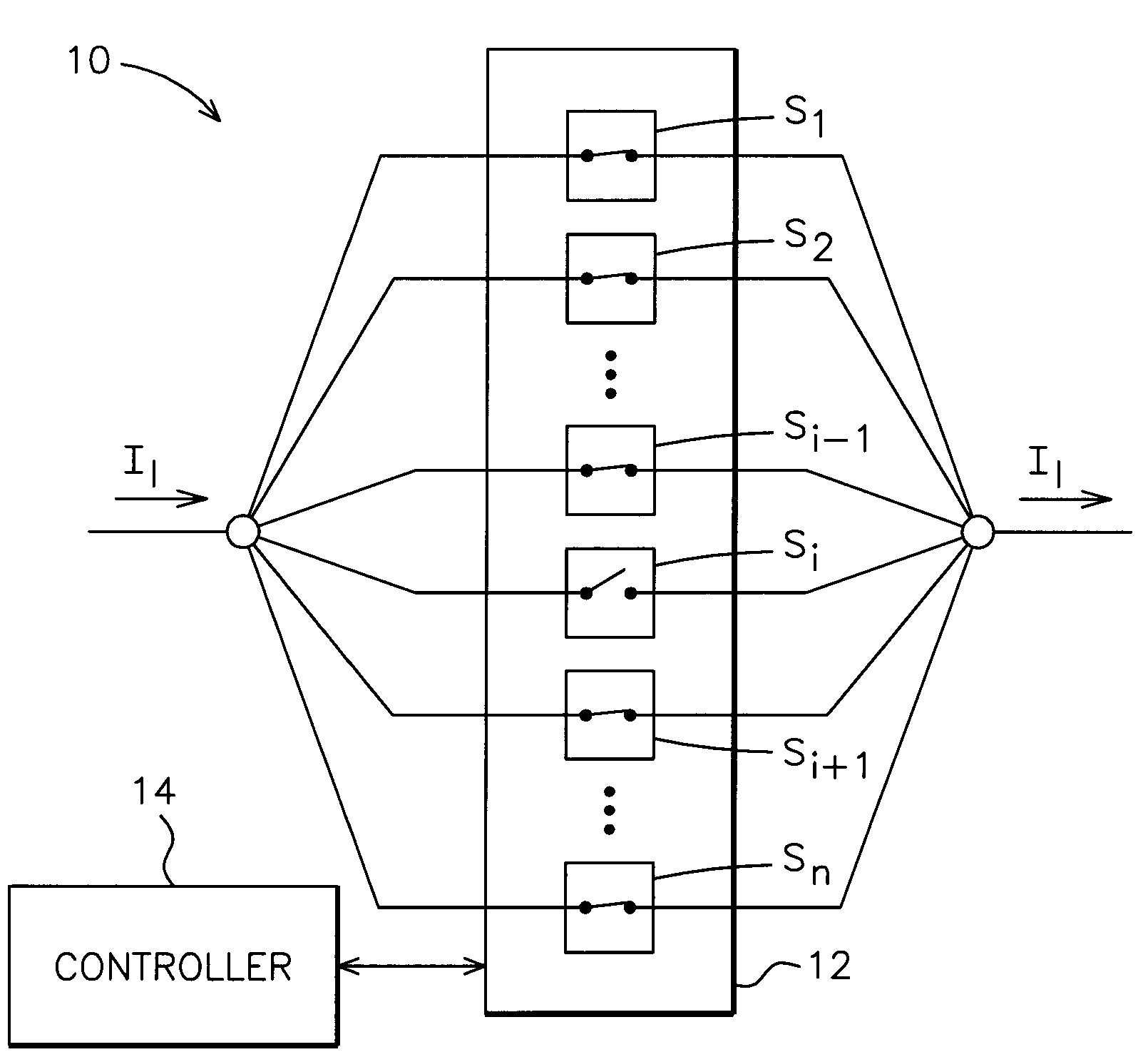
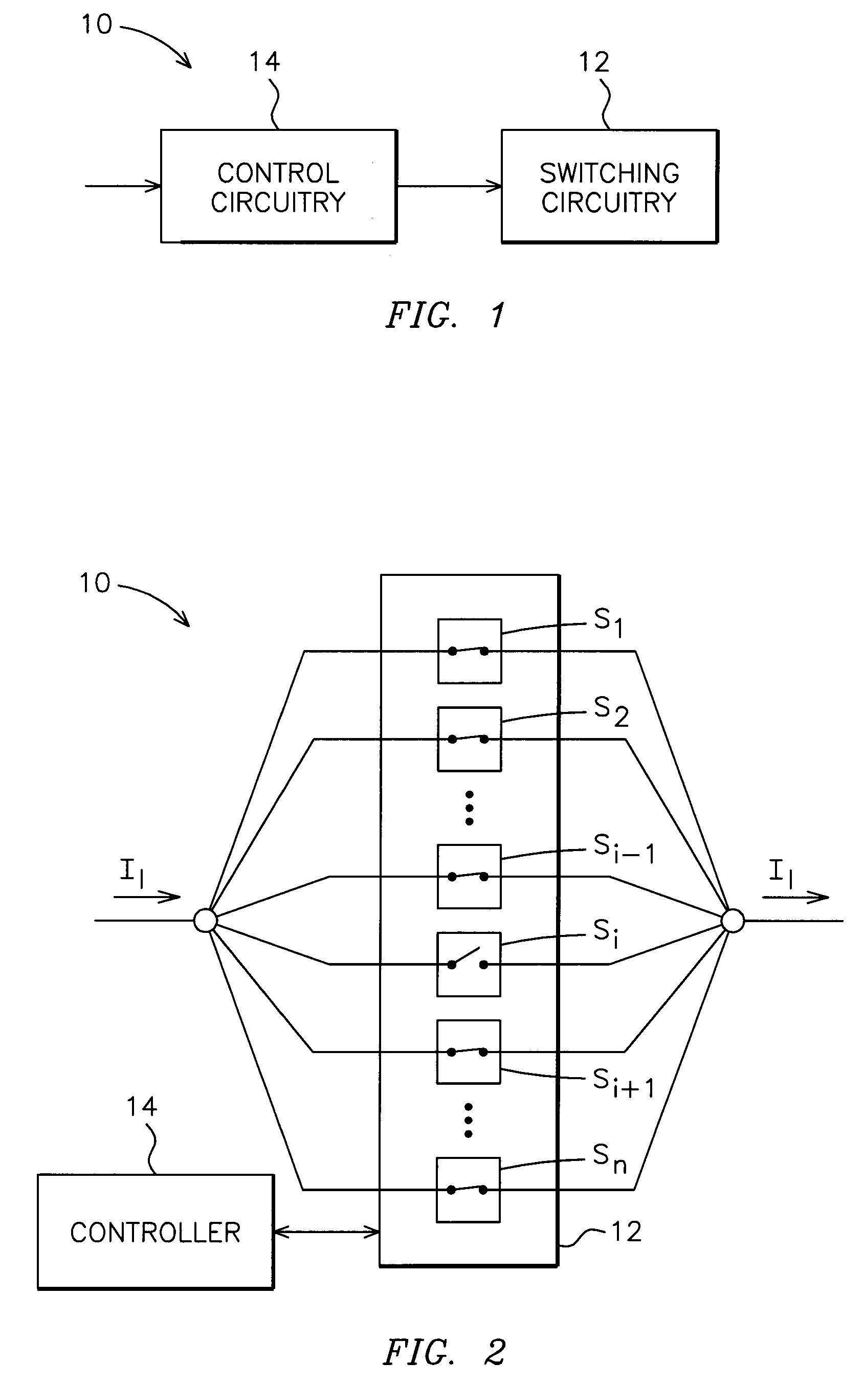
[0016]In accordance with one or more embodiments of the present invention, a system including micro-electromechanical system (MEMS) switching circuitry will be described herein. In the following detailed description, numerous specific details are set forth in order to provide a thorough understanding of various embodiments of the present invention. However, those skilled in the art will understand that embodiments of the present invention may be practiced without these specific details, that the present invention is not limited to the depicted embodiments, and that the present invention may be practiced in a variety of alternative embodiments. In other instances, well known methods, procedures, and components have not been described in detail.

[0017]Furthermore, various operations may be described as multiple discrete steps performed in a manner that is helpful for understanding embodiments of the present invention. However, the order of description should not be construed as to impl...


PUM


Abstract

A system that includes micro-electromechanical system switching circuitry, such as may be made up of a plurality of micro-electromechanical switches, is provided. The plurality of micro-electromechanical switches may generally operate in a closed switching condition during system operation. A controller is coupled to the electromechanical switching circuitry. The controller may be configured to actuate at least one of the micro-electromechanical switches to a temporary open switching condition while a remainder of micro-electromechanical switches remains in the closed switching condition to conduct a load current and avoid interrupting system operation. The temporary open switching condition of the switch is useful to avoid a tendency of switch contacts to stick to one another.

Description

BACKGROUND OF THE INVENTION[0001]Embodiments of the invention relate generally to electrical circuitry, and, more particularly, to micro-electromechanical system (MEMS) based switching devices, and, even more particularly, to a system and method for avoiding a tendency of switch contacts to stick to one another without interrupting system operation.[0002]A circuit breaker is an electrical device designed to protect electrical equipment from damage caused by faults in the circuit. Traditionally, most conventional circuit breakers include bulky electromechanical switches. Unfortunately, these conventional circuit breakers are large in size thereby necessitating use of a large force to activate the switching mechanism. Additionally, the switches of these circuit breakers generally operate at relatively slow speeds. Furthermore, these circuit breakers are disadvantageously complex to build and thus expensive to fabricate. In addition, when contacts of the switching mechanism in conventi...

Claims


Application Information

Patent Timeline
Patent Type & Authority Applications(United States)
IPC IPC(8): H01H57/00H02H3/08
CPCH01H59/0009H01H2071/008H01H2059/0018H01H59/00B81B7/04
Inventor O'BRIEN, KATHLEEN ANNSUBRAMANIAN, KANAKASABAPATHIHEDGES, NICOLE CHRISTINE REEVESIDELCHIK, MICHAEL SOLOMONSCHELENZ, OWEN JANNIS
Owner GENERAL ELECTRIC CO
Why Eureka
Try Eureka