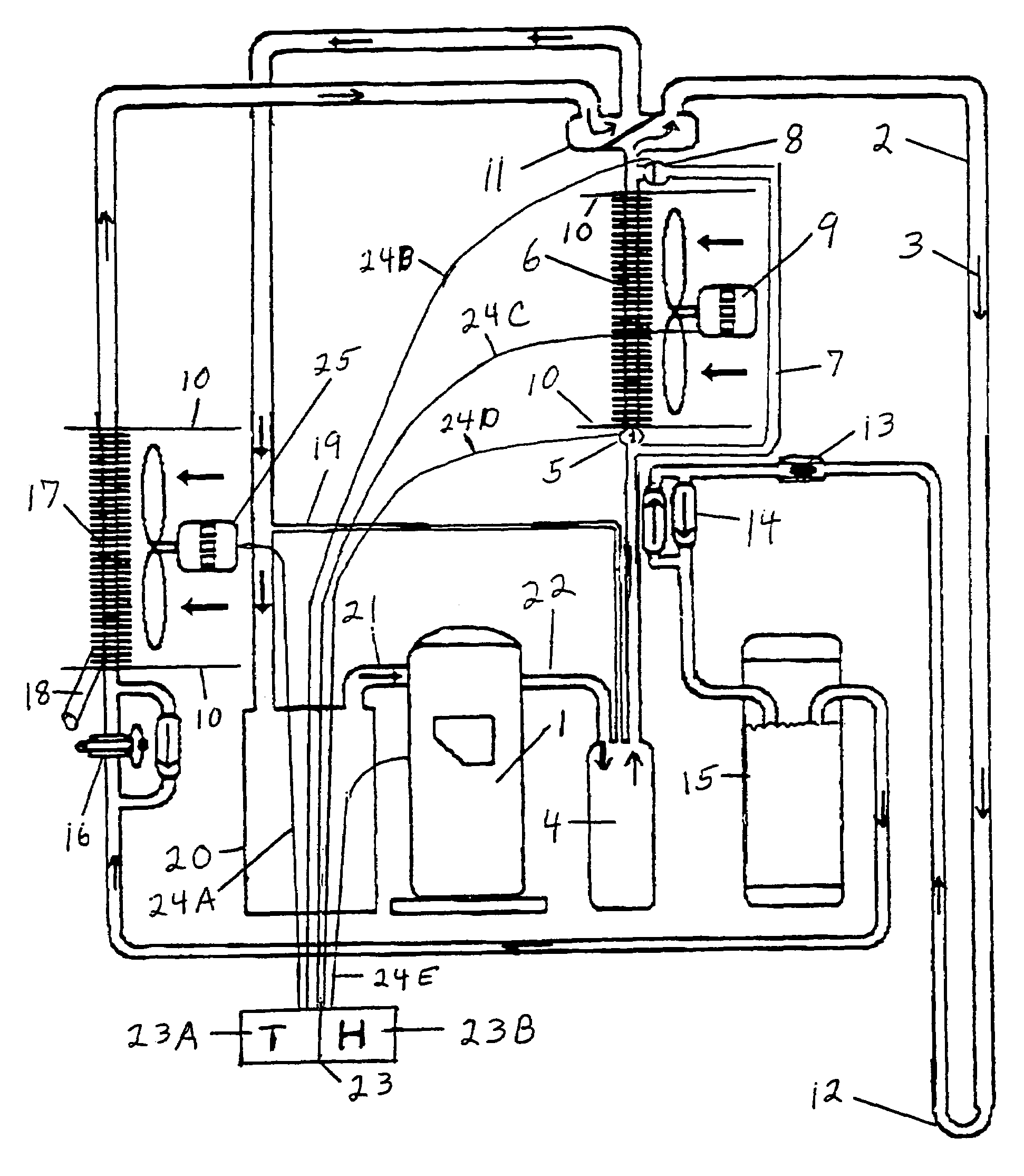
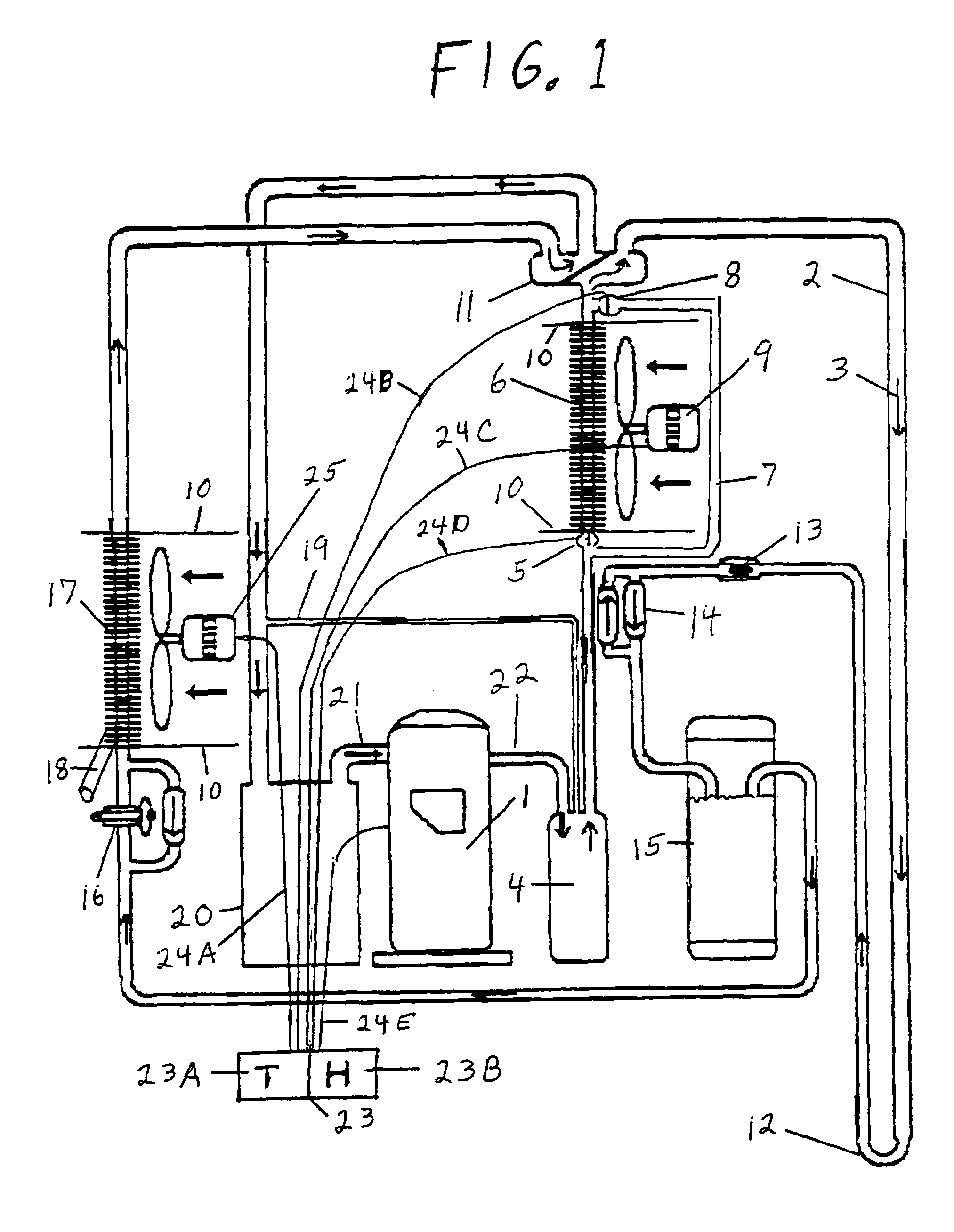
[0030]More specifically, to accomplish this means of removing humidity once the heat pump system's
thermostat setting has been reached, a secondary interior
air handler would be placed within the
refrigerant transport loop at a location between the system's compressor and one of the sub-
surface heat exchange tubing, the refrigerant to circulating water to ground heat exchange loop, and the exterior air heat exchange loop, so as to transfer all or most of the heat removed by the first and primary cooling mode
air handler back into the interior air before the heat is rejected into the exterior heat exchange means, which is comprised of one of the earth, water, and exterior air. The warmed air supplied by the secondary and additional
air handler would temper the otherwise cooled air traveling through the return air ducts, so as to permit the system to remain in operation without cooling the interior air to so low a point as to call for the
thermostat to become uncomfortably cool. Preferably, the cooled air and the warmed air would be mixed together within the supply ductwork, which is well understood by those skilled in the art, prior to the supply air being distributed into the interior
air space by the supply air ducts. Further, since all or most (most means all, less the extra heat generated by means of the externally powered system components, such as the compressor, the fans, and the like) of the removed interior air heat is being replaced back into the interior air before it reaches at least one of the ground and the water in a geothermal system application, there is no undue
heat load or stress placed upon the sub-
surface heat exchange area or upon a
geothermal heat pump system by means of an extended system operation in the dehumidification mode.
[0035]The secondary air handler should be sized to remove all the heat extracted from the interior air by the primary air handler operating in the cooling mode so as to maintain a neutral interior
air temperature, with the additional heat generated by the operation of the system's compressor and fans still being rejected into the exterior heat exchange means comprised of one of the ground
heat sink, the water to ground
heat sink, and the exterior air
heat sink. The rejection of such a minimal amount of system mechanical operational heat will not impose any undue stress upon a geothermal system's sub-
surface heat exchange field, will not impose any stress upon an air
source system's exterior air heat exchange means, and will prevent the interior air from becoming too warm too soon.
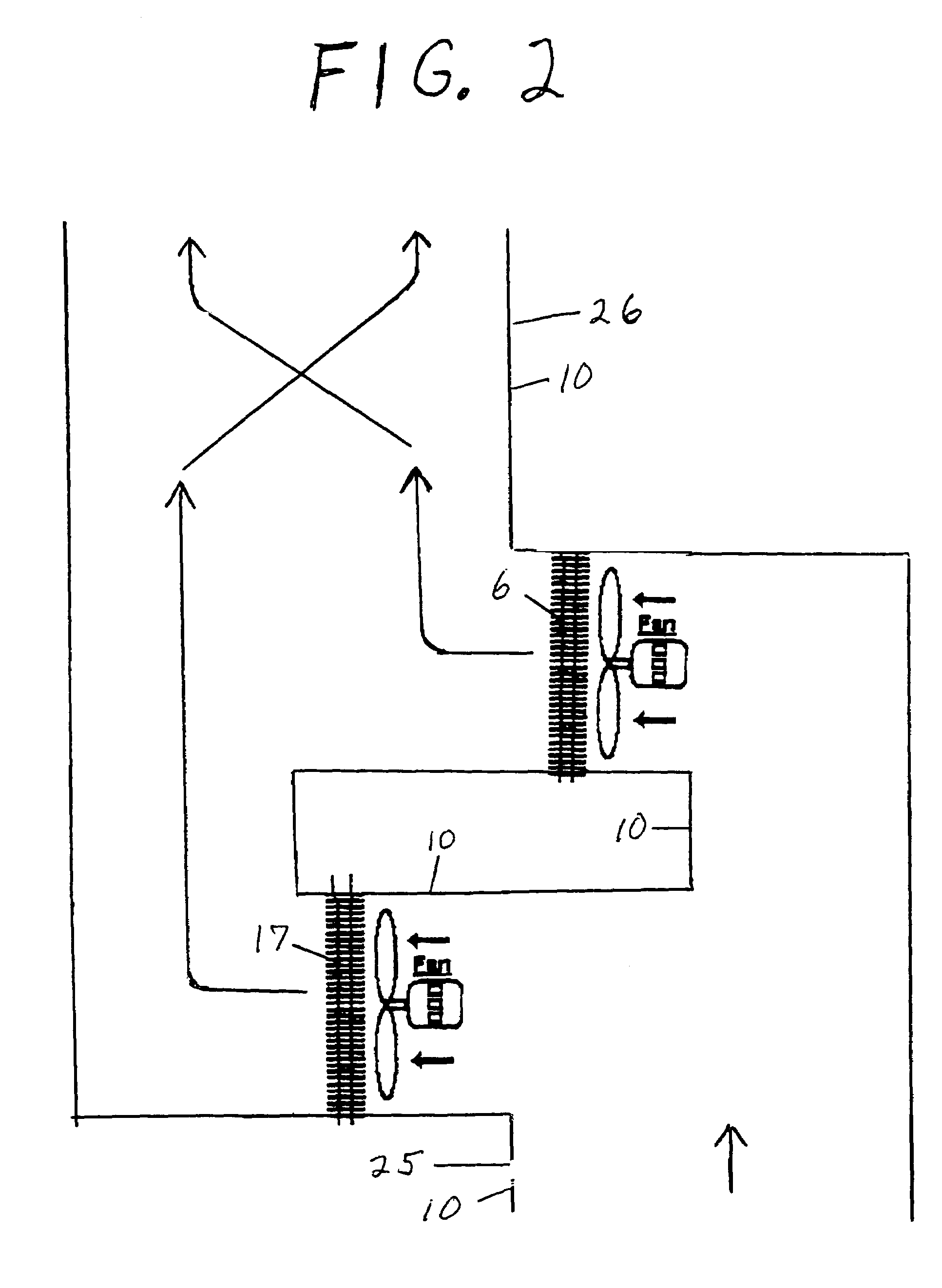
[0038]There is an additional
advantage of utilizing a secondary interior air heat exchange means (second air handler) for optional dehumidification purposes. Namely, the incorporation of the second air handler in the hot gas line enables one to downsize the second air handler so as to
gain warmer air in the heating mode, and simultaneously enables one to upsize the first and primary interior air heat exchange means (first air handler) so as to
gain cooler air in the cooling mode and so as to remove more humidity in the dehumidification mode. Typically, in a reverse-cycle heat pump application, the standard one air handler is sized somewhere between the smaller heating mode optimum size and the larger cooling mode optimum size, so as to reasonably accommodate both operational
modes.
[0040]When operating in the dehumidification mode with a first air handler that is about twice the size of the second air handler, the
airflow over both air handlers must still be equalized, less the rate in the second interior air heat exchange means (the second air handler) that is equivalent to the additional heat of compression generated by means of at least one of the system's compressor and externally powered components. The multiple manners of equalizing the
airflow over both air handlers is well understood by those skilled in the art, and may, for one example, be easily accomplished by decreasing the fan speed, and resulting cubic feet per minute (“CFM”)
airflow, of the first air handler so as to match the desired CFM rate of the second air handler.

