Adjustable vertical accumulator for slitting operation

a vertical accumulator and slitting technology, which is applied in the direction of transportation and packaging, manufacturing tools, instruments, etc., can solve the problems of equipment for performing, the center portion of the strip is produced in the coil, and the forming roll of the rolling mill is difficult to prevent the forming roll from bowing

Inactive Publication Date: 2009-04-30
PAPANIA JAMES F
View PDF16 Cites 7 Cited by
  • Summary
  • Abstract
  • Description
  • Claims
  • Application Information

AI Technical Summary

Benefits of technology

[0007]The present invention is designed to overcome the deficiencies of the prior art discussed above. It is an object of the present invention to provide an accumulator in a slitting and rewinding operation that eliminates the need for a pit yet maintains proper tension on each of the individual slit coils.

Problems solved by technology

In the continuous production of rolling of metal strip, it is difficult to prevent the forming rolls of a rolling mill from bowing by a slight amount.
Thus when the single strip is coiled, the center portion of the single strip has a tendency to increase in diameter at a faster rate than the edge portions which results in producing greater tension in the center portion of the strip within the coil.
Since the coils being unwound, slit and rewound and the equipment for performing these operations are extremely heavy, the entire operation is normally performed on the ground floor of a facility and on a solid concrete slab.
Depending on the terrain, it may or may not be possible to dig and properly finish the necessary pit.
But even when it can be done, it is obviously an expensive process.
Furthermore, once the pit is formed, its depth cannot be changed without going through additional substantial expense.

Method used


Image

  • Adjustable vertical accumulator for slitting operation
  • Adjustable vertical accumulator for slitting operation
  • Adjustable vertical accumulator for slitting operation

Examples


Embodiment Construction

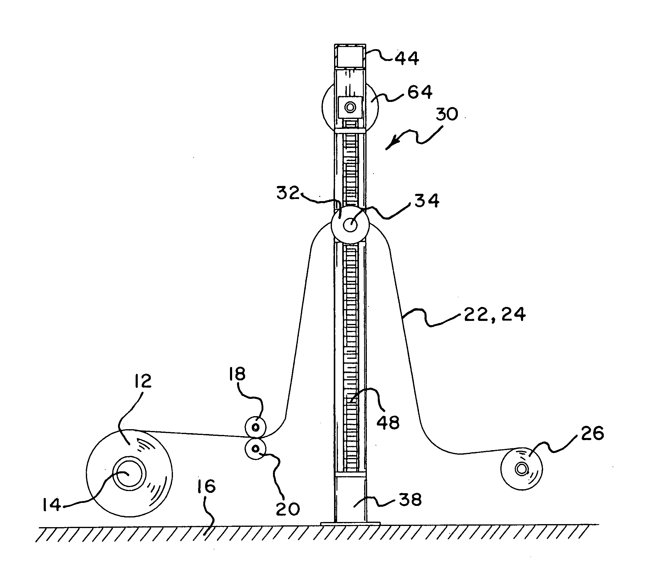
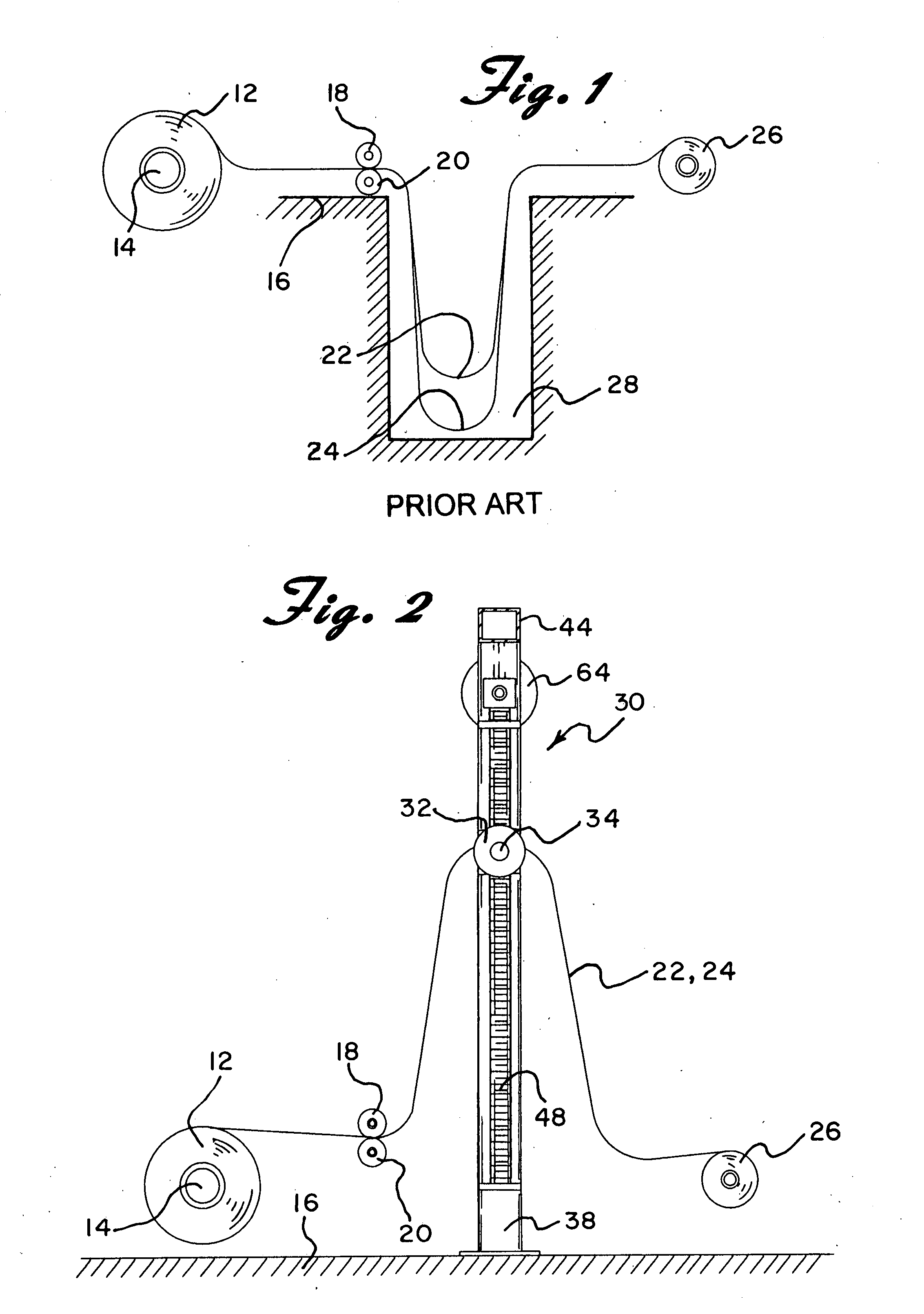
[0016]Referring now to the drawings in detail wherein like reference numerals have been used throughout the various figures to designate like elements, there is shown diagrammatically in FIG. 1 a prior art system upon which the present invention is based. As is well known in the art, a sheet metal unwinding, slitting and rewinding operation starts with a wide coil of sheet metal 12 wound about a horizontal axis 14 which is mounted on the floor 16 for rotation about the axis 14. A pair of slitting rollers 18 and 20 slit the sheet metal 12 into a plurality of strips such as shown at 22 and 24. The slit strips 22 and 24 are then rewound at a rewind station where the individual strips are individually rewound into a plurality of smaller coils 26. Located between the slitter rollers 18 and 20 and the rewinding station is an accumulator in the form of a pit 28 dug downwardly beneath the floor 16. All of the foregoing is well known in the art. Accordingly, only a brief description of the s...


PUM

PropertyMeasurementUnit
heightaaaaaaaaaa
rotationaaaaaaaaaa
widthaaaaaaaaaa

Abstract

A vertical accumulator for use in a sheet metal unwinding, slitting and rewinding operation accumulates the slack created in the plurality of strips cut from an initial wide coil so that the proper tension can be maintained on the individual strips being rewound. The accumulator includes an elongated mandrel mounted for rotation about a horizontal axis parallel to the axis of the original sheet metal coil and is arranged such that all of the plurality of cut strips pass over the top of the mandrel. The mandrel is located above the height of the coil and above the height of the slitter and the rewound individual strips. A plurality of disks mounted on the mandrel separate the cut strips from each other. Upwardly extending threaded rotatable rods located on either side of the sheet metal strips carry holders that releasably support the mandrel. Rotation of the rods causes the holders to move up or down to thereby adjust the height of the mandrel.

Description

BACKGROUND OF THE INVENTION[0001]The present invention is directed toward apparatus for handling coils of sheet metal strip which includes apparatus for unwinding a coil of single metal strip for slitting to form a plurality of separate strips of predetermined width for rewinding the strips into individual coils and, more particularly, toward a vertical accumulator that maintains continuous tension in each strip during the rewinding operation.[0002]In the continuous production of rolling of metal strip, it is difficult to prevent the forming rolls of a rolling mill from bowing by a slight amount. This is particularly true with wider strips which is caused, in part by the weight of the forming rolls, but primarily by the enormous radial loading on the rolls as they progressively compress the metal strip to reduce its thickness. As a result, the metal strip which is formed usually varies in cross-sectional thickness with the center portion of the strip being a few thousandths of an in...

Claims


Application Information

Patent Timeline
Patent Type & Authority Applications(United States)
IPC IPC(8): B65H35/02
CPCB21C49/00B65H20/32B65H2701/173B65H2403/52B65H2301/4148
Inventor PAPANIA, JAMES F.
Owner PAPANIA JAMES F
Why Eureka
Try Eureka