High speed manufacture of injection-moulded part

a manufacturing process and high-speed technology, applied in the direction of food shaping, press ram, food shaping, etc., can solve the problem of pressing plate for a very long time, and achieve the effect of flexible use, convenient and easy controllable balan

Inactive Publication Date: 2009-04-30
ALCAN PACKAGING BEAUTY SERVICES
View PDF2 Cites 9 Cited by
  • Summary
  • Abstract
  • Description
  • Claims
  • Application Information

AI Technical Summary

Benefits of technology

[0021]Preferably, to obtain an even finer and more easily controllable balance of the flows of plastic material, the injection head is equipped with dosing actuators that are supplied by said runners and which allow a controlled quantity of material to be injected into the mould cavity associated with said runner. It is possible, for example, to provide chambers of predetermined volume in the injection head, each of these chambers being traversed by a runner. A piston, the stroke of which is preferably adjustable, moves in the chamber under the effect of an actuator, for example. When the piston is retracted, the chamber is filled with the molten plastic material. When the piston moves forward, the plastic material is injected under pressure in the direction of the associated mould cavity. As will be demonstrated in the example given below, the dosing actuator can be associated with a valve which, when the moulding assembly is not bearing against the injection head, allows the channel of the feed nozzle to be closed and the chamber of the dosing actuator to be filled and which, when the moulding assembly is bearing against the injection head, blocks the admission port of the runner in the chamber of the dosing actuator and places said chamber in communication with the channel of the feed nozzle.
[0022]Another advantage of using individualised dosing actuators resides in the injection head's flexibility of use. An injection head comprising as many dosing actuators and valves as there are runner outlets (intended to supply a mould cavity) can remain permanently fastened to the injection press, while the moulding assemblies designed to be supplied by this injection head include a number of cavities less than or equal to the number of runner outlets. To accomplish this, said dosing actuators and said valves can simply be actuated individually, typically by a control distributor, so that the dosing actuators are not actuated and to maintain closed the valves corresponding to the cavities that are not to be filled and to thus prevent the flow of plastic material through the feed nozzles.

Problems solved by technology

This process thus differs from the prior art in that the block containing the hot runners, separated from the rest of the moulding tool, can be mounted to the injection press plate for a very long time.

Method used


Image

  • High speed manufacture of injection-moulded part
  • High speed manufacture of injection-moulded part
  • High speed manufacture of injection-moulded part

Examples


Embodiment Construction

Example (FIGS. 3 to 5)

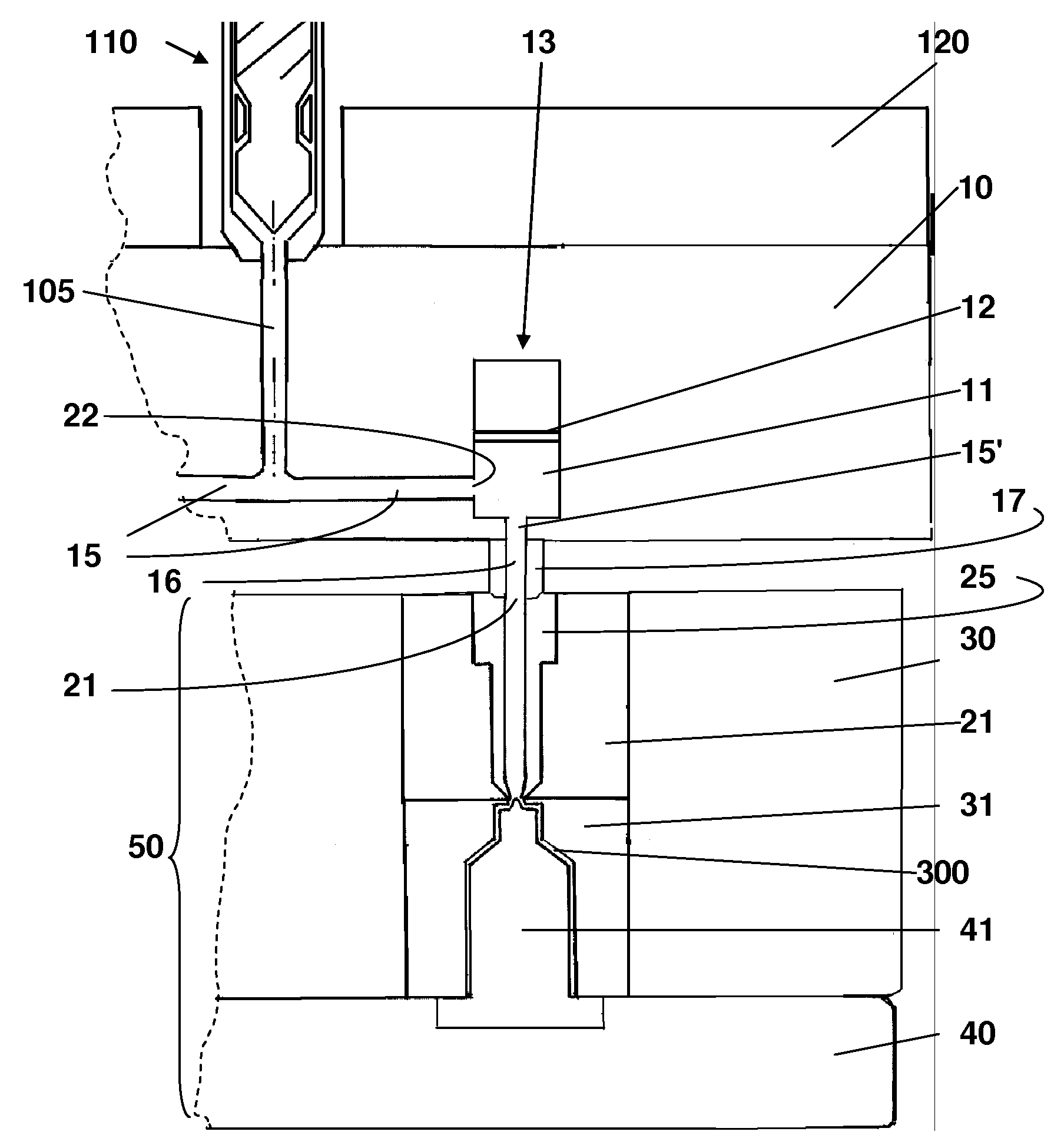
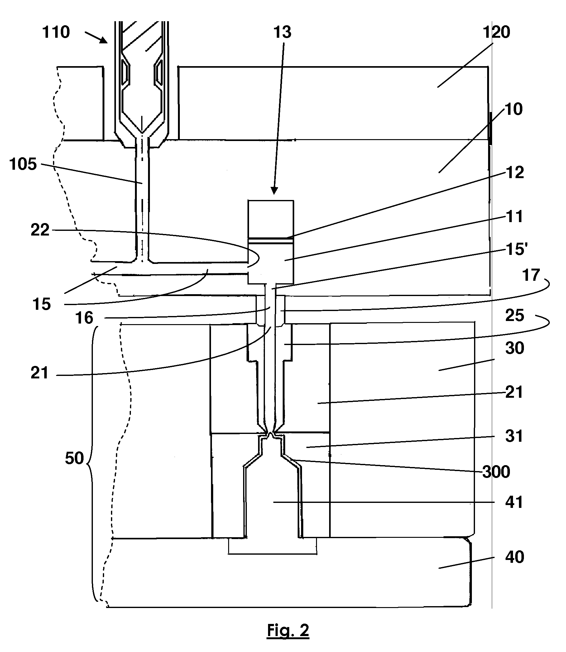
[0037]The machine illustrated in FIGS. 3 to 5 is used to mould 180 plastic parts per minute, represented in this example by a flat-bottomed recipient with a slightly conical side wall.

[0038]It comprises an injection press 100 on which is mounted an injection head 10 and a rotary table 400 with five sectors each equipped with a group of 6 moulding assemblies 50. The rotary table 400 is indexed and operates in a step-by-step manner in order to serve five workstations. One of these stations is used to remove the moulded parts. Another of these stations is used for the injection of the moulded parts. This station includes the injection press 100 and the actuators 500 which allow the moulding assemblies 50 to be placed against the injection head 10 secured to the plate of the injection press.

[0039]The injection press 100 is represented in FIG. 3 by only the injection unit 110 and the feed hopper 105 of the injection unit 110, by which the mixing screw is fed with pe...


PUM

PropertyMeasurementUnit
pressureaaaaaaaaaa
temperatureaaaaaaaaaa
bearing forceaaaaaaaaaa

Abstract

A multi-cavity moulding process, using a moulding tool including an injection head integral with the injection press and a moulding assembly, the plastic material being injected under pressure and distributed in runners provided in the injection head which is equipped with heating elements, the moulding assembly including two mobile parts the assembly of which allows the mould cavities to be formed and the spreading of which allows the moulded parts to be ejected. The moulding assembly also includes a manoeuvring device that opens, closes and locks the mobile parts, where none of the mobile parts (30 and 40) of the moulding assembly is secured to the injection head, the moulding assembly coming into contact with the injection head and bearing on it only when it is closed in position and locked in order to fill the mould cavities.

Description

BACKGROUND OF THE INVENTION[0001]The invention concerns a high-speed manufacturing process for producing injection-moulded parts. We shall illustrate this process by using flexible tube heads or flexible tube blanks as the moulded parts, which must be manufactured at rates exceeding 100 parts per minute, typically between 200 and 400 parts per minute.[0002]The flexible tubes are intended to store and distribute fluid to pasty products, such as cosmetic products, pharmaceutical products, hygiene products or food products. They have a head made of plastic material(s), including a shoulder and a neck equipped with a dispensing orifice, and a flexible cylindrical skirt (axisymmetrical or otherwise) made of one or more plastic materials.[0003]Generally speaking, the flexible tubes are made by assembling two parts manufactured separately: a flexible cylindrical skirt of given length (typically 3 to 5 times the diameter) and a head comprising a neck with dispensing orifice and a shoulder c...

Claims


Application Information

Patent Timeline
Patent Type & Authority Applications(United States)
IPC IPC(8): B29C45/04B29C45/56B29C45/06
CPCB29C45/06B29C45/28B29C45/2725
Inventor CHASLIN, DOMINIQUE
Owner ALCAN PACKAGING BEAUTY SERVICES
Why Eureka
Try Eureka