Magnetic Field Compensation Apparatus for Cathode Ray Tube

a cathode ray tube and compensation device technology, applied in the field of cathode ray tubes, can solve the problems of color impurities on the screen, significantly more difficult to design adequate shielding for all orientations, north, south, east and wes

Inactive Publication Date: 2009-04-30
THOMSON LICENSING SA
View PDF2 Cites 4 Cited by
  • Summary
  • Abstract
  • Description
  • Claims
  • Application Information

AI Technical Summary

Problems solved by technology

Horizontal magnetic fields on the other hand can lead to first order register changes causing color impurities on the screen.
Changing the CRT orientation from East to West reverses the direction of the register shift and it becomes significantly more difficult to design adequate shielding for all orientations, North, South, East, and West.

Method used


Image

  • Magnetic Field Compensation Apparatus for Cathode Ray Tube
  • Magnetic Field Compensation Apparatus for Cathode Ray Tube
  • Magnetic Field Compensation Apparatus for Cathode Ray Tube

Examples


Embodiment Construction

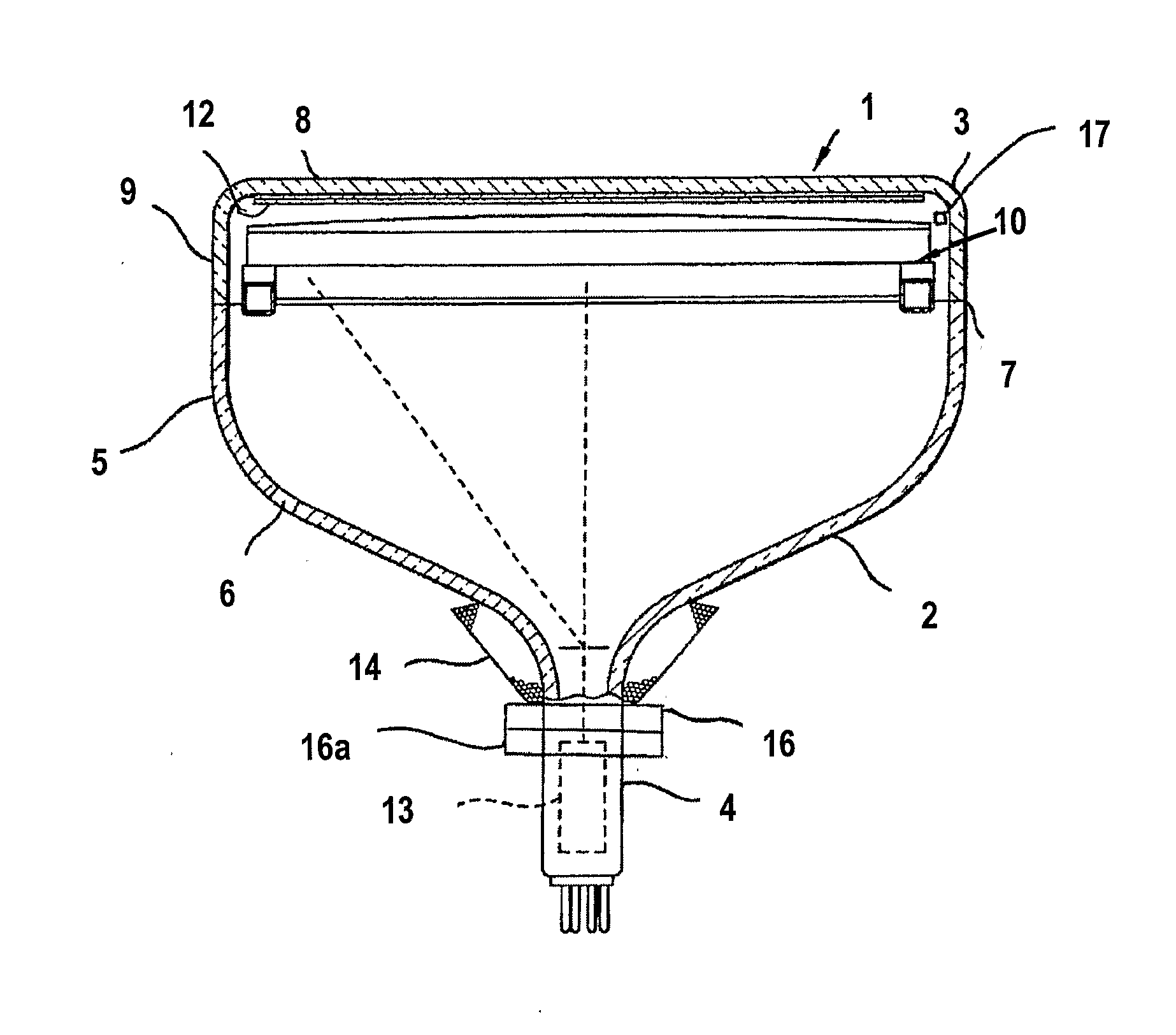
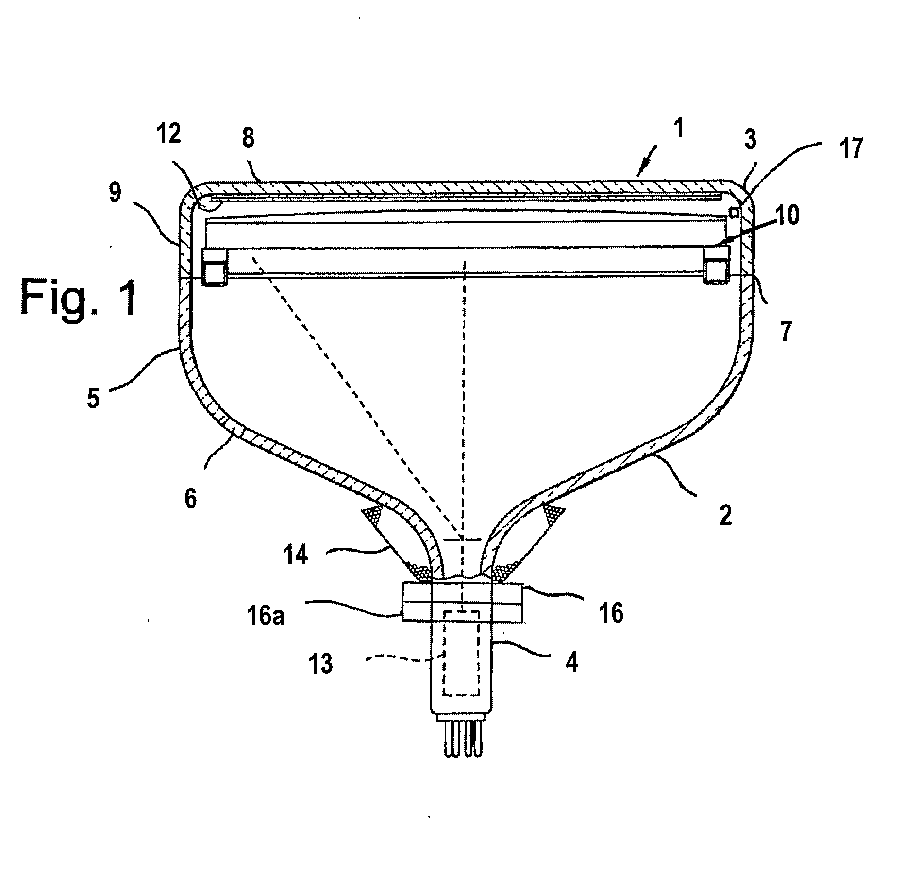
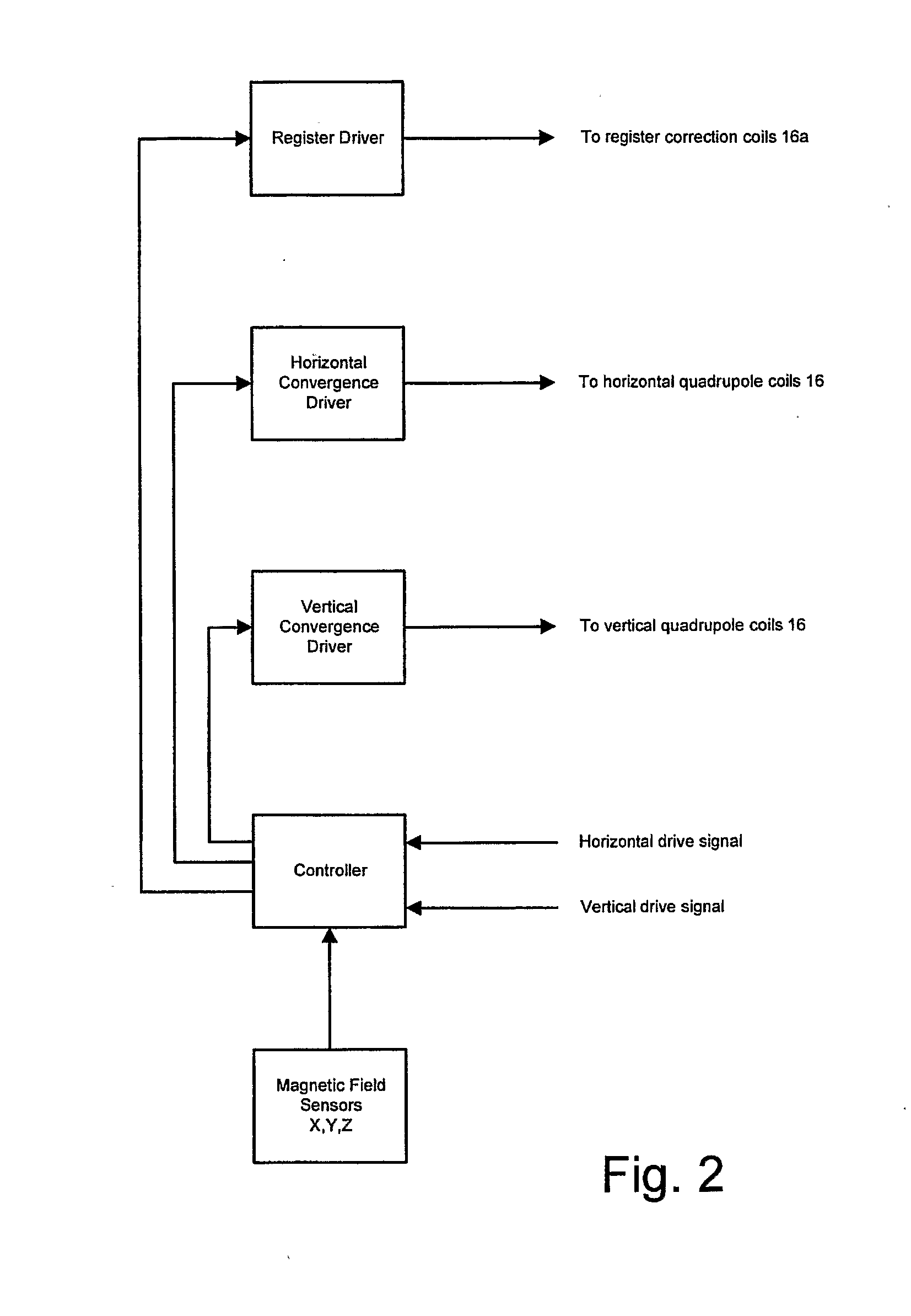
[0014]The invention provides an electronic compensation system having a sensor 17 which detects the orientation and magnitude of the local earth's magnetic field relative to that of the tube location and a set of compensation coils for correcting register errors that may be introduced by the local magnetic fields. FIG. 1 shows a cathode ray tube (CRT) 1, for example a W76 wide screen tube having a glass envelope 2 comprising a rectangular faceplate panel 3 and a tubular neck 4 connected by a funnel 5. The funnel 5 has an internal conductive coating (not shown) that extends from an anode button 6 toward the faceplate panel 3 and to the neck 4. The faceplate panel 3 comprises a viewing faceplate 8 and a peripheral flange or sidewall 9, which is sealed to the funnel 5 by a glass frit 7. A three-color phosphor screen 12 having a plurality of alternating phosphor stripes is carried by the inner surface of the faceplate panel 3. The screen 12 is a line screen with the phosphor lines arran...


PUM


Abstract

A cathode ray tube (CRT) having a glass envelope is disclosed. The glass envelope is formed of a rectangular faceplate panel and a tubular neck connected thereto by a funnel. An electron gun is positioned in the neck for directing electron beams toward the faceplate panel. A yoke is positioned in the neighborhood of the funnel-to-neck junction. The yoke has windings configured to apply a horizontal deflection yoke field and a vertical deflection yoke field to the beams. At least one magnetic field sensor is located near the glass envelope for sensing an ambient magnetic field environment of the CRT. A controller receives a signal from the magnetic field sensor. Register correction coils are mounted in the vicinity of the neck and are dynamically controlled by the controller to shift the beams. Quadrupole coils are applied to the neck and have adjacent poles of alternating polarity such that the resultant magnetic field being dynamically controlled by the controller based on the magnetic field sensor signal moves outer ones of the beams to correct the misconvergence caused by the register correction.

Description

CROSS-REFERENCE TO RELATED APPLICATIONS[0001]This application claims the benefit of U.S. Provisional Patent Application Ser. No. 60 / 534,458, entitled “Magnetic Field Compensation Apparatus for Cathode Ray Tube” and filed Jan. 6, 2004, which is incorporated by reference herein in its entirety.FIELD OF THE INVENTION[0002]The invention is related to Cathode Ray Tubes (CRT) and more particularly to a magnetic field compensation system for use in such CRT.BACKGROUND OF THE INVENTION[0003]The color rendition of a CRT image can be affected by the ambient magnetic field in the vicinity of the CRT. This ambient field is generally caused by the Earth's magnetic field and can be affected by local magnetic fields and magnetic materials in the area. This field can be considered to have a vertical component and a horizontal component. The horizontal component is normally oriented North to South. In a given location the relationship of the vertical component with respect to the path of the CRT ele...

Claims


Application Information

Patent Timeline
Patent Type & Authority Applications(United States)
IPC IPC(8): H01J29/70H01J29/00H04N9/29
CPCH01J29/003H04N9/29H01J2229/5687H01J29/705H01J29/00H01J29/70
Inventor GOROG, ISTVANBARBIN, ROBERT LLOYD
Owner THOMSON LICENSING SA
Why Eureka
Try Eureka