

Signal generating apparatus and class-d amplifying apparatus
- Summary
- Abstract
- Description
- Claims
- Application Information
AI Technical Summary
Benefits of technology
Problems solved by technology
Method used
Image

Examples
modification 1
[0044](1) Modification 1
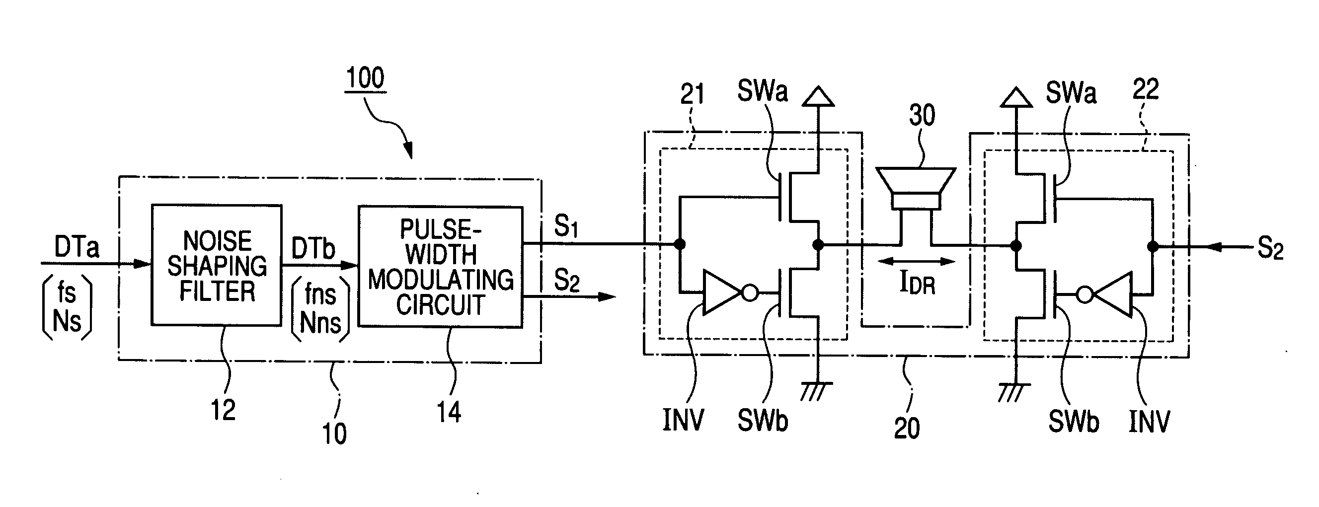
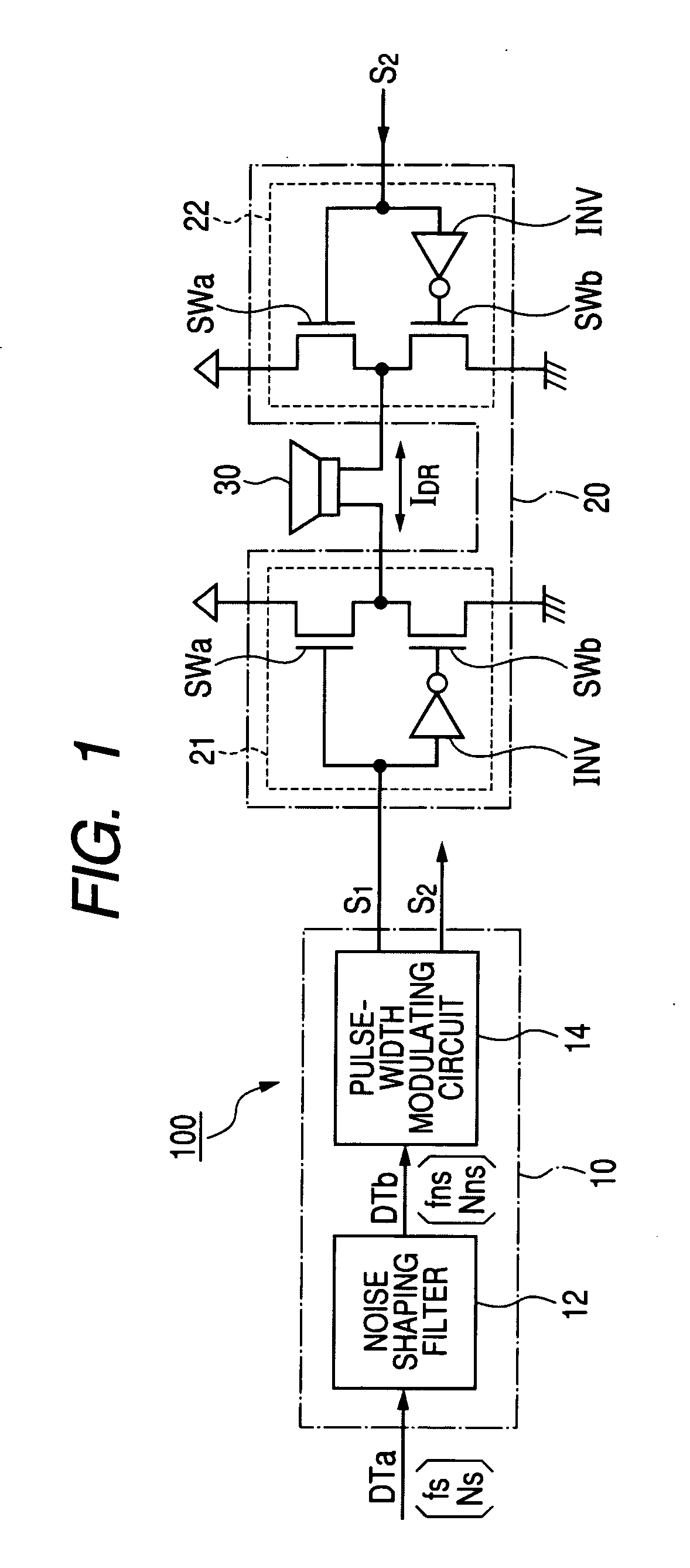
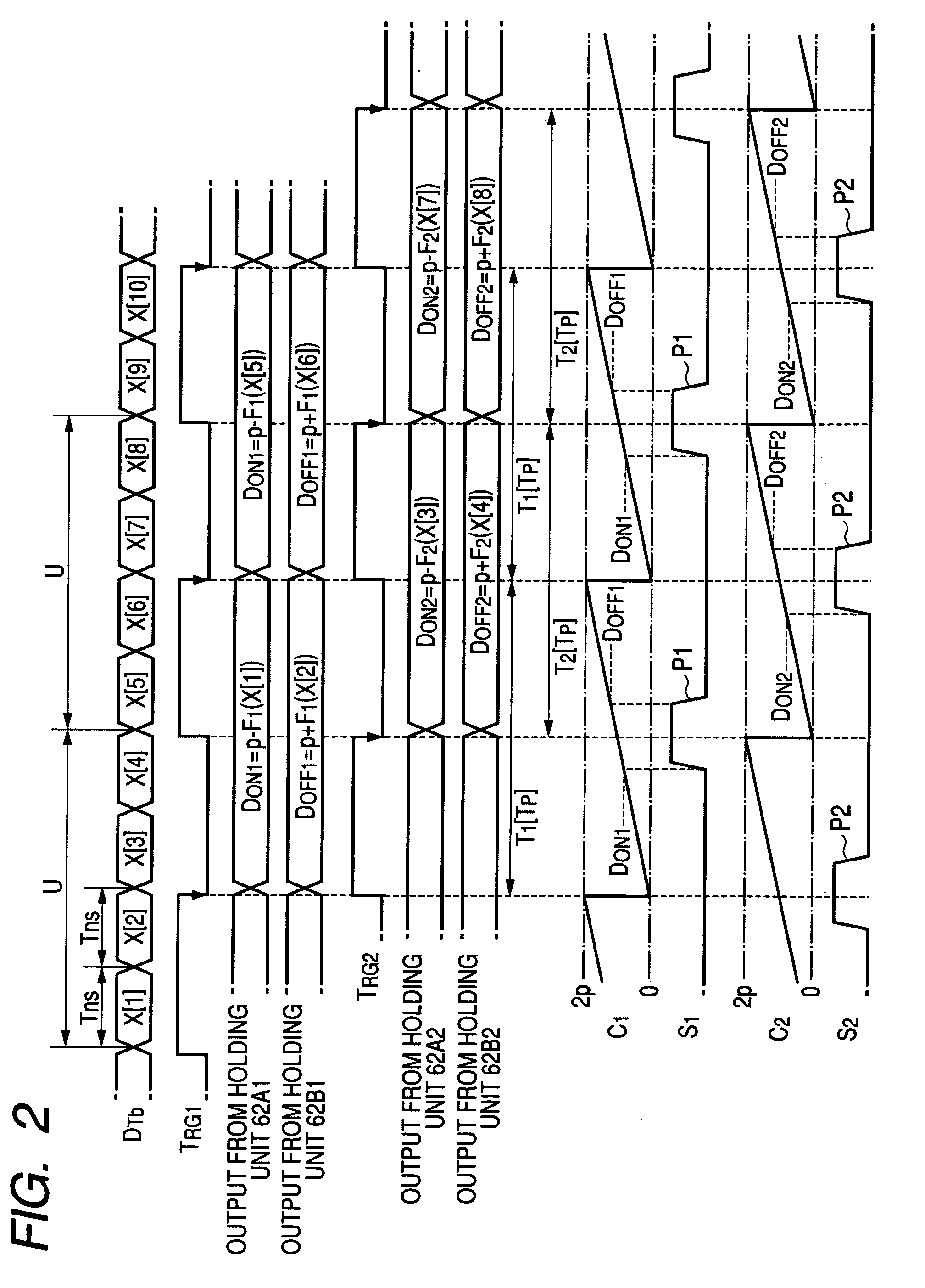
[0045]The relationship between the numeral values of the respective data “X” of the data series “ID Tb1”, and the function values F1(X) and F2(X) is not limited only to the exemplified relationship of FIG. 4. For example, as indicated in FIG. 7, the conversion functions “F1” and “F2” may be alternatively defined in such a manner that when the numeral value of the data “X” becomes smaller than a predetermined value (−x0), the function value “F1(X)” becomes zero, whereas when the numeral value of the data “X” exceeds the predetermined value (x0), the function value F2(X) becomes zero. In the embodiment of FIG. 7, when the numeral value of the data “X” becomes smaller than the predetermined value (−x0), the pulse width of the pulse P1 becomes zero, whereas when the numeral value of the data “X” exceeds the predetermined value (x0), the pulse width of the pulse P2 becomes zero. As a consequence, a current amount of a drive current “I DR” flowing through the load ...
modification 2
[0046](2) Modification 2
[0047]In the above-described embodiments, the signal generating apparatus10 generates both the pulse-width modulation signals “S1” and “S2” of the two systems. Alternatively, a total number of pulse-width modulation signals “S” may be properly changed. FIG. 10 is a timing chart for explaining operations for generating pulse-width modulation signals “S1” to “S3” of 3 systems by the signal generating apparatus 10. A unit series “U” obtained by segmenting the data series “D Tb” contains 6 pieces of data “X” (X[1] to X[6]). The pule-width modulation signals “S1” and “S2” may be generated in response to the data X[1] to X[4] within the unit series “U” in a similar manner to the above-described embodiment. On the other hand, as to a pulse “P3” of the pulse-width modulation signal “S3”, a time point of a front edge thereof is set in response to the fifth data X[5], and a time point of a rear edge thereof is set in response to the sixth data X[6] within the unit seri...
PUM
 Abstract
Description
Claims
Application Information