Liquid Crystal Display

a liquid crystal display and display screen technology, applied in the field of liquid crystal display, can solve problems such as difficult to solve, and achieve the effect of superior advantage, large screen, and maintaining the image quality of liquid crystal tv

Active Publication Date: 2009-04-30
PANASONIC LIQUID CRYSTAL DISPLAY CO LTD +1
View PDF1 Cites 22 Cited by
  • Summary
  • Abstract
  • Description
  • Claims
  • Application Information

AI Technical Summary

Benefits of technology

[0026]According to the backlight device of the present invention, since the growth in screen size and the super low-profiling of the light guide plate can be achieved at the same time, and further, the dots-visualization in the screen of the liqui

Problems solved by technology

In the related art, there are many problems in the backlight technology (the backlight device), in particular in achieving the growth

Method used


Image

  • Liquid Crystal Display
  • Liquid Crystal Display
  • Liquid Crystal Display

Examples


Embodiment Construction

[0042]A backlight device (a side edge backlight) and a liquid crystal display equipped with the backlight device according to an embodiment of the present invention will hereinafter be explained with reference to accompanying drawings.

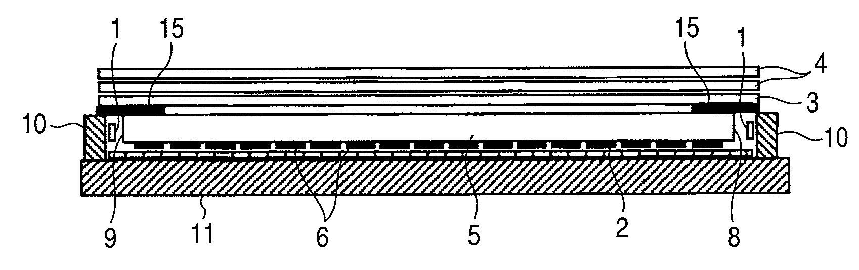
[0043]FIG. 5A is a cross-sectional view showing the backlight device according to the embodiment of the present invention. The dots 6 are formed on the lower surface of the light guide plate 5. FIG. 5B is a diagram for explaining the dots 6 formed on the lower surface of the light guide plate 5. The light source 1 formed of a linear light source (a fluorescent bulb such as a cold-cathode tube) or of a plurality of point light sources (e.g., light emitting diodes) arranged in a line is disposed so as to be opposed to an end face 8, an end face 9 on the opposite side, or both of the end faces 8 and 9 of the light guide plate 5 made of a translucent material. There are provided the reflecting plate 2 for reflecting light disposed below the lower surface o...


PUM


Abstract

In a liquid crystal display equipped with a side edge backlight device, visualization of “a dot provided to a light guide plate” in the vicinity of the light source while keeping the luminance of the display screen. The shapes and the arrangement of the light diffusing dots (dots) provided to the principal surface of the light guide plate of the backlight device are made different between the area of the principal surface in the vicinity of the light source and the other areas, thereby adjusting the whiteness of the light guide plate in the vicinity of the light source. The plurality of dots formed in the vicinity of the light source are each composed of a first section for diffusing the light propagating the light guide plate, and a second section surrounded by the first section and less capable of diffusing the light, and are disposed in the vicinity of the light source in a zigzag manner.

Description

CLAIM OF PRIORITY[0001]The present application claims priority from Japanese application serial no. JP2007-275902, filed on Oct. 24, 2007, the content of which is hereby incorporated by reference into this application.BACKGROUND OF THE INVENTION[0002]1. Technical Field[0003]The present invention relates to a member used for a liquid crystal display, such as a backlight device (a backlight), and to a liquid crystal display using the member.[0004]2. Related Art[0005]In recent years, low-profiling, cost reduction, and power reduction of liquid crystal television sets (hereinafter referred to as liquid crystal TVs) with a large screen have been promoted, and widespread thereof is now in progress. In order for further low-profiling such large-screen liquid crystal TVs, super low-profiling of the backlight devices needs to be achieved. As a conventional backlight device for such large-screen liquid crystal TVs, a direct backlight shown in FIG. 2 is used.[0006]The direct backlight shown in...

Claims


Application Information

Patent Timeline
IPC IPC(8): G02F1/13357
CPCG02B6/0043G02B6/0061G02B6/0055G02B6/0051
Inventor TANIGUCHI, HITOSHIKONNO, AKITOYO
Owner PANASONIC LIQUID CRYSTAL DISPLAY CO LTD
Why Eureka
Try Eureka