Method for measuring micro-particle

Inactive Publication Date: 2009-04-30
SONY CORP
View PDF10 Cites 10 Cited by
  • Summary
  • Abstract
  • Description
  • Claims
  • Application Information

AI Technical Summary

Benefits of technology

[0015]Not only the flow channel for reference is provided, but also the property measurements are performed by using the one or more reference materials, thereby making it possible to reflect the results of the measurements of the properties of the one or more reference materials in detection of the property information on the material to be measured in consideration of a state as well of the micro-particle caused to flow through the flow channel for measurement.
[0016]According to the present invention, the micro-particle caused to flow through the flow channel can be precisely measured.

Problems solved by technology

However, merely providing the flow channel for reference causes a problem that it may be impossible to precisely grasp a reference value which differs every measurement.
In addition, there is encountered a problem that a work efficiency is low because it takes time to perform a work for an advance preparation for the measurement.

Method used


Image

  • Method for measuring micro-particle
  • Method for measuring micro-particle
  • Method for measuring micro-particle

Examples


Embodiment Construction

[0025]Hereinafter, embodiments of the present invention will be described in detail with reference to the accompanying drawings. It is noted that the accompanying drawings or the like show typical embodiments of the present invention, and thus the scope of the present invention is not intended to be construed in a limiting sense by the accompanying drawings or the like.

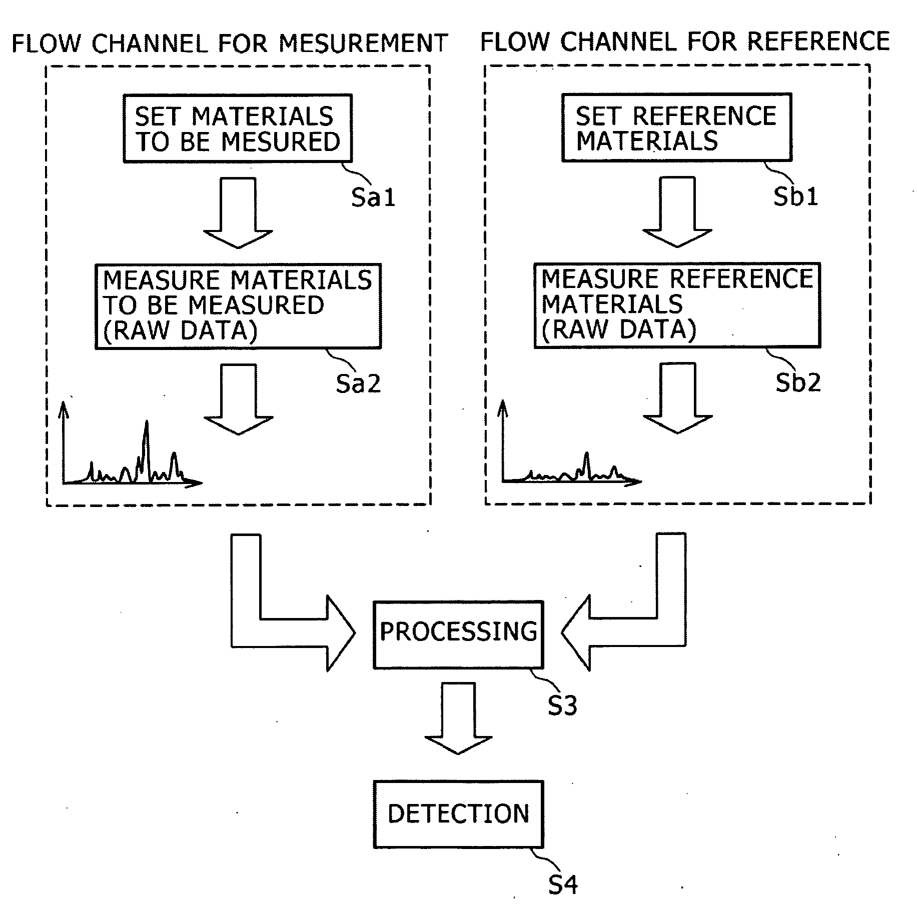
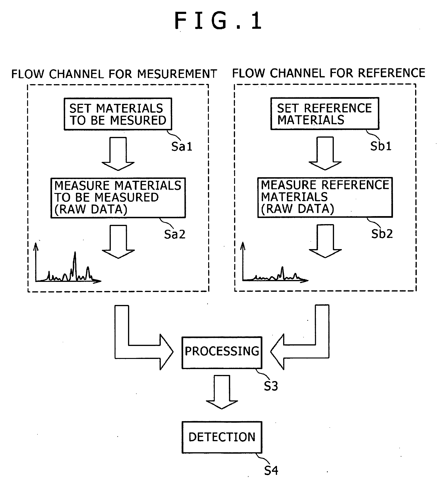
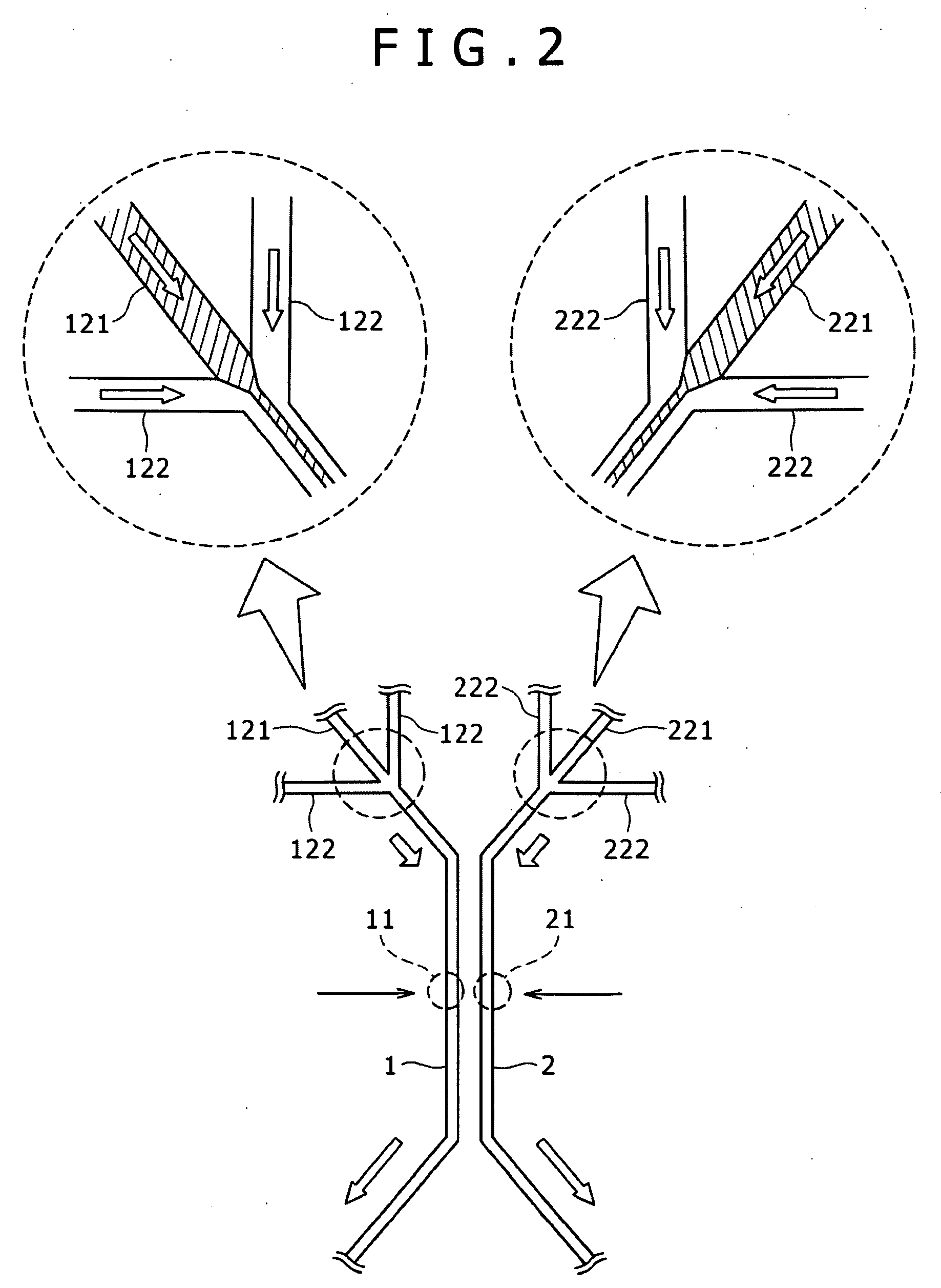
[0026]FIG. 1 is a flow chart explaining an outline of a method for measuring a micro-particle according to the present invention. FIG. 2 is a conceptual view showing a structure of a flow channel used in a method for measuring a micro-particle according to an embodiment of the present invention. Also, FIGS. 3A and 3B are respectively spectral graphs explaining an example of processing performed in the method for measuring a micro-particle according to the embodiment of the present invention. Hereinafter, the method for measuring a micro-particle according to the embodiment of the present invention will be described in...


PUM


Abstract

A method for measuring a micro-particle caused to flow through a flow channel, includes the steps of: measuring a property of a material to be measured as a micro-particle in a predetermined position of a flow channel for measurement, and measuring properties of one or more reference materials in a predetermined position of a flow channel for reference while the material to be measured is caused to flow through the flow channel for measurement, and the one or more reference materials are caused to flow through the flow channel for reference; and processing a result of the measurement of the material to be measured in accordance with a result of the measurements of the one or more reference materials.

Description

CROSS REFERENCES TO RELATED APPLICATIONS[0001]The present invention contains subject matter related to Japanese Patent Application JP 2007-278436 filed in the Japan Patent Office on Oct. 26, 2007, the entire contents of which being incorporated herein by reference.BACKGROUND OF THE INVENTION[0002]1. Field of the Invention[0003]The present invention relates to a method for measuring a micro-particle, and more particularly to a technique for measuring a micro-particle caused to flow through a flow channel.[0004]2. Description of Related Art[0005]In recent years, a technique for analyzing a small amount of specimen caused to flow through a micro-flow channel or the like in the micro-flow channel has been applied to a wide range of fields, including a bio-related analysis, a chemical analysis, and the like. Moreover, this technique has been expected to be further developed based on attracting a great deal of attention in an application field such as a photonic system, and a development ...

Claims


Application Information

Patent Timeline
IPC IPC(8): G01N15/00
CPCG01N15/1012G01N15/1056G01N2015/149G01N2015/1081G01N15/1404G01N15/1023G01N2015/1028G01N15/149
Inventor SHINODA, MASATAKA
Owner SONY CORP
Why Eureka
Try Eureka