Eureka AIR delivers breakthrough ideas for toughest innovation challenges, trusted by R&D personnel around the world.

Coupling lens and optical information recording/reproducing device having the same

Inactive Publication Date: 2009-04-30
HOYA CORP
View PDF9 Cites 0 Cited by
  • Summary
  • Abstract
  • Description
  • Claims
  • Application Information

AI Technical Summary

Benefits of technology

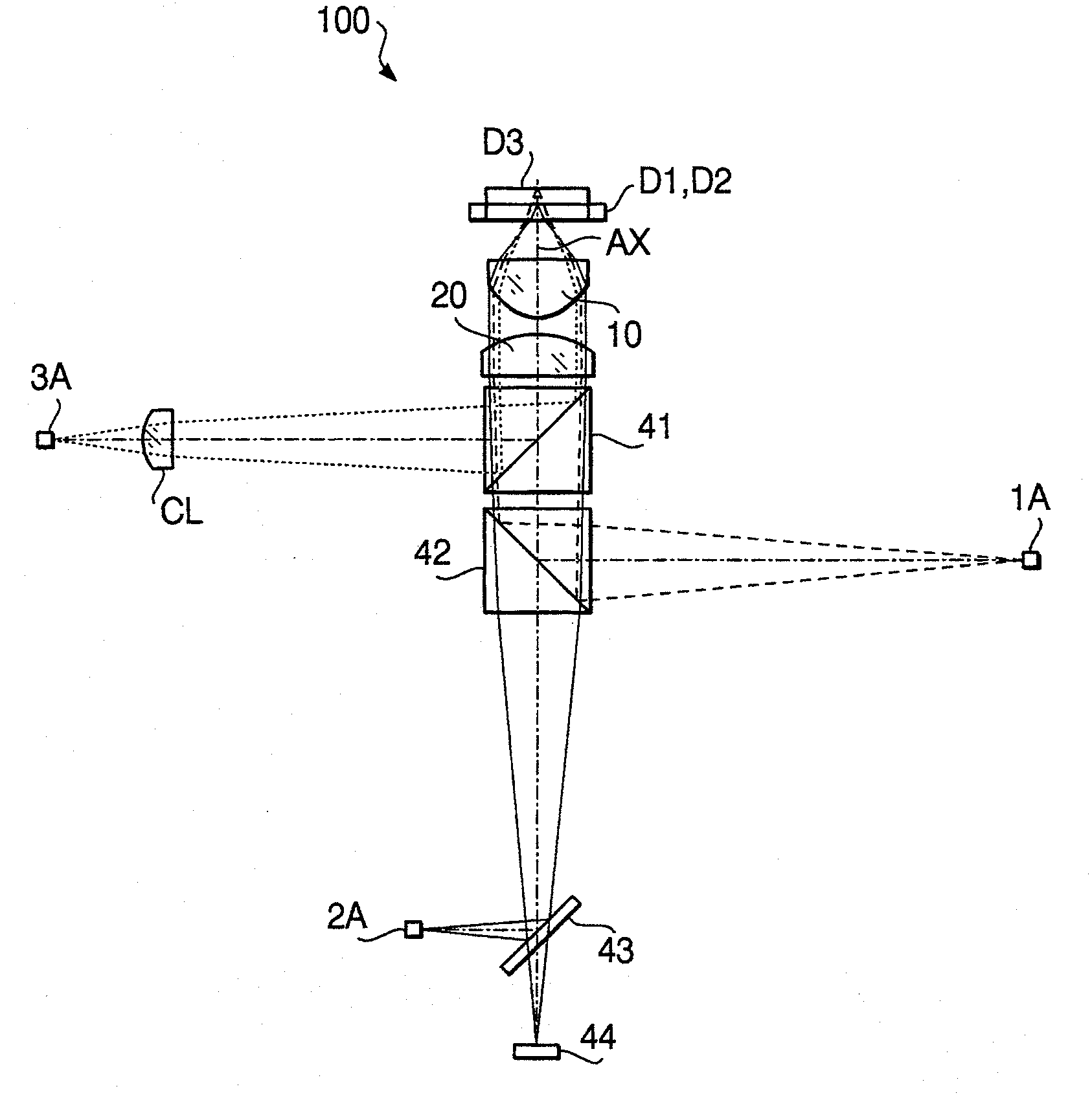
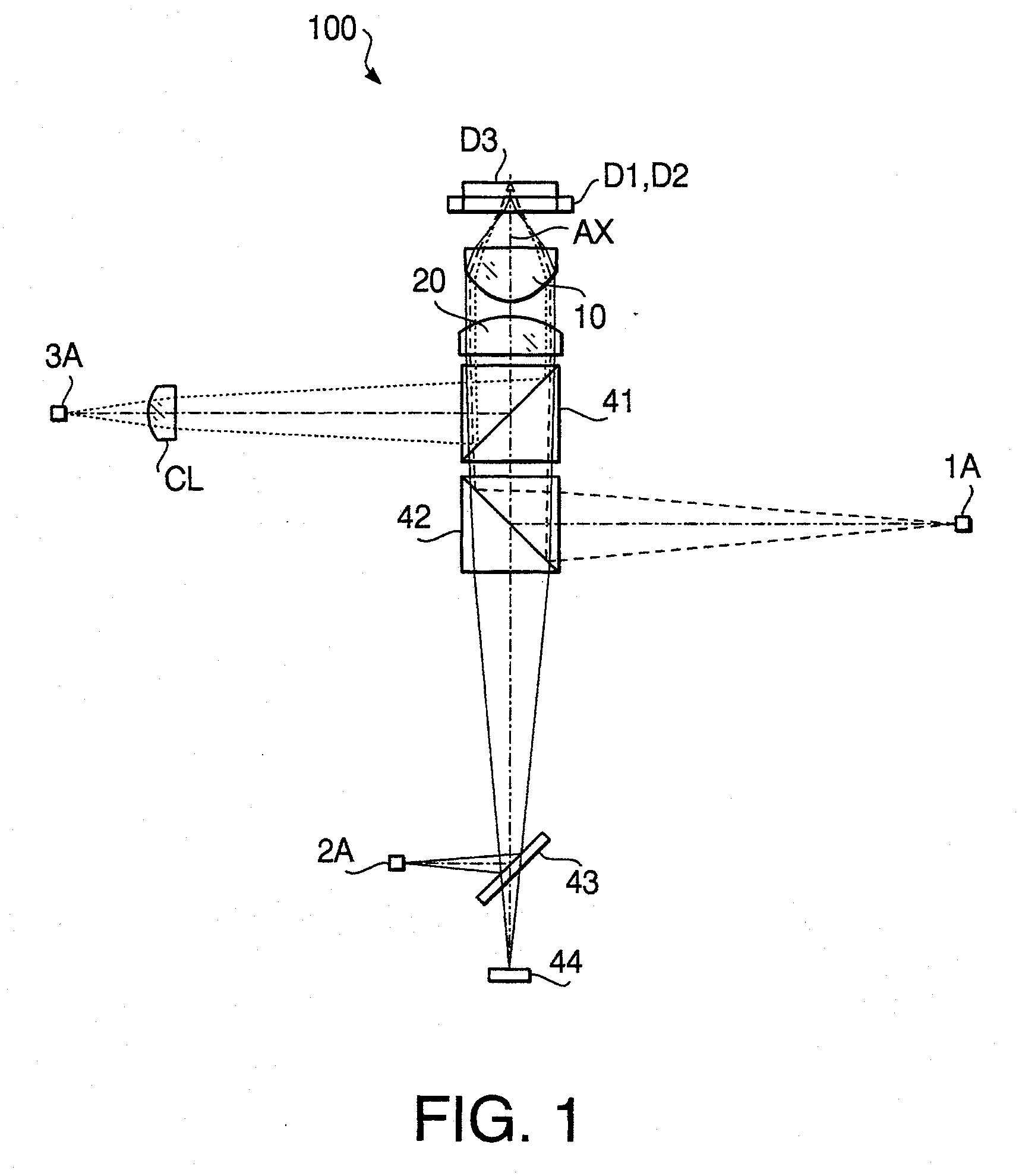
[0010]The present invention is advantageous in that it provides at least one of a coupling lens capable of suppressing change of a relative positional relationship between an object point and an image point due to change in refractive index while achieving a low cost and a simple structure, and an optical information recording / reproducing device in which such a coupling lens is employed.
[0014]By configuring the coupling lens such that the value Z satisfy the above described condition, it becomes possible to maintain a relative positional relationship between an object point and an image point at a suitable state without using a diffraction structure.

Problems solved by technology

Such a property of a lens made of resin causes a considerable amount of change of the positional relationship between an object point and an image point with respect to the position of the lens.
However, if change in refractive index of the coupling lens which is placed only on an approaching optical path of a light beam proceeding to an optical disc (but is not placed on a returning optical path of the light beam returning from the optical disc) occurs, the following problems occur.
First, the light beam emerging from the coupling lens may have an unintended degree of divergence.
If the degree of divergence of the light beam emerging from the coupling lens changes, the spherical aberration is caused.
In this case, it becomes difficult to form a suitable beam spot for information recording or information reproducing on a record surface of the optical disc.
Second, since typically a photoreceptor for receiving light reflected from the record surface of the optical disc is placed at a position having a conjugate relationship with an image point of the coupling lens, the conjugate relationship is lost if the image point of the coupling lens changes due to change in refractive index or linear expansion and thereby it may become difficult for the photoreceptor to execute an accurate detecting operation.
However, it is noted that the diffraction structure increases the manufacturing difficulty of the coupling lens and thereby increases the manufacturing cost of the coupling lens.

Method used


Image

  • Coupling lens and optical information recording/reproducing device having the same
  • Coupling lens and optical information recording/reproducing device having the same
  • Coupling lens and optical information recording/reproducing device having the same

Examples


first example

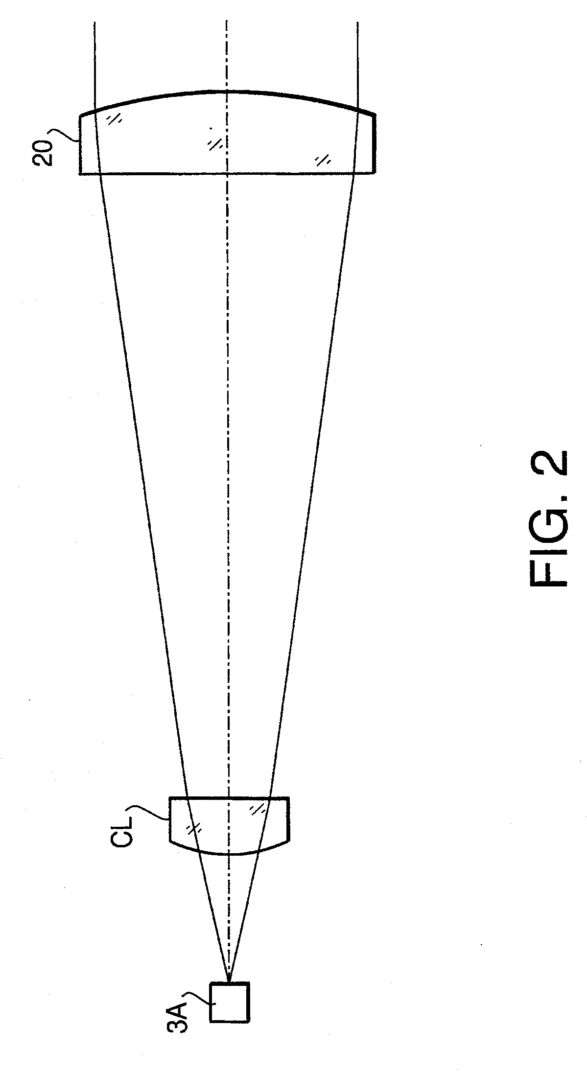
[0048]Table 1 shows a concrete numerical configuration of the coupling lens CL according to a first example. Table 2 shows values of Z and the parameters concerning the above described equation (E1) of the coupling lens shown in Table 1.

TABLE 1focal length5.761magnification1.262r13.240r2−116.800t1.700L−1.166L′−2.581n1.550

TABLE 2A0.708B−0.255C−1.097D0.949E−0.006F0.367G0.995H0.202Z0.000

[0049]The image working distance L′ shown in Table 1 is a design value. As shown in Table 2, the coupling lens CL according to the first example satisfies the conditions (1) and (2).

second example

[0050]The coupling lens CL according to a second example is designed such that both of the first and second surfaces CL1 and CL2 are aspherical surfaces. Table 3 shows a concrete numerical configuration of the coupling lens CL according to the second example. Table 4 shows the conical coefficient and aspherical coefficients defining the first surface CL1 of the coupling lens CL. Table 5 shows the conical coefficient and aspherical coefficients defining the second surface CL2 of the coupling lens CL.

TABLE 3focal length189.049magnification1.125effective diameter (h)3.000of CL1r1−11.500r2−10.834t1.500L−11.779L′−14.959n1.550

TABLE 4K0.00000A41.3780E−04A62.4020E−06

TABLE 5K0.00000A48.2210E−05A61.5340E−06

[0051]Table 6 shows values of Z and the parameters concerning the above described equation (E1) of the coupling lens CL shown in Table 3.

TABLE 6A0.624B0.639C−0.968D12.324E−0.058F0.146G0.951H0.062Z0.230

[0052]As shown in Table 6, the coupling lens CL according to the second example satisfies ...


PUM


Abstract

There is provided a coupling lens used in an optical information recording / reproducing device for recording information to and / or reproducing information from an optical disc. The coupling lens includes a first surface and a second surface, wherein the coupling lens is configured to satisfy a following condition (1):−0.80≦Z≦0.40   (1),wherein a value Z is obtained from a following equation (E1):Z=n(L′)L′=(A-B)(D-E)-(F-G)(H-I).(E1)

Description

BACKGROUND OF THE INVENTION [0001]The present invention relates to a coupling lens forming an optical system of a device, such as an optical information recording / reproducing device for recording information to and / or reproducing information from an optical disc.[0002]In general, an optical information recording / reproducing device is configured such that the degree of divergence of a light beam emitted by a light source is converted by a coupling lens and the converted light beam is converged by an objective lens onto a record surface of an optical disc, such as a CD or a DVD, being used. Incidentally, in this specification, the “optical information recording / reproducing devices” include devices for both information reproducing and information recording, devices exclusively for information reproducing, and devices exclusively for information recording. In the following, the term “compatibility” is used to mean that the optical information recording / reproducing device ensures the inf...

Claims


Application Information

Patent Timeline
IPC IPC(8): G11B7/00
CPCG11B7/1378G11B2007/0006G11B7/13922
Inventor TASHIRO, YOSHIYUKITAKEUCHI, SHUICHI
Owner HOYA CORP
Why Eureka
Eureka Blog
Learn More