
Eureka
For R&D, Eureka makes reading and utilizing patents & technical documents easy.
Eureka AIR
Designed for self-driven R&D workflows. Generate viable solutions, solve complex R&D challenges, empower your innovation with AI.

Eureka Materials
Designed for material experts only. Revolutionize your material R&D, from search, analyze, to developing new materials.

TechResearch
Generate reliable direction feasibility study reports for your R&D in just a few steps.

TechSeek
Discover and master advanced knowledge NOW. Basics, ideas, possibilities, all at once.

TechMind
As an expert in R&D Theories, TechMind can generates customized viable solutions instantly.

TechRisk
Analyze your overall solution with one click, know your potential R&D risks in advance.

TechMonitor
Get weekly tech updates, stay abreast of the latest tech innovations and key insights.
Floating pin joint assembly
- Summary
- Abstract
- Description
- Claims
- Application Information
AI Technical Summary
Problems solved by technology
Method used
Image

Examples
Embodiment Construction
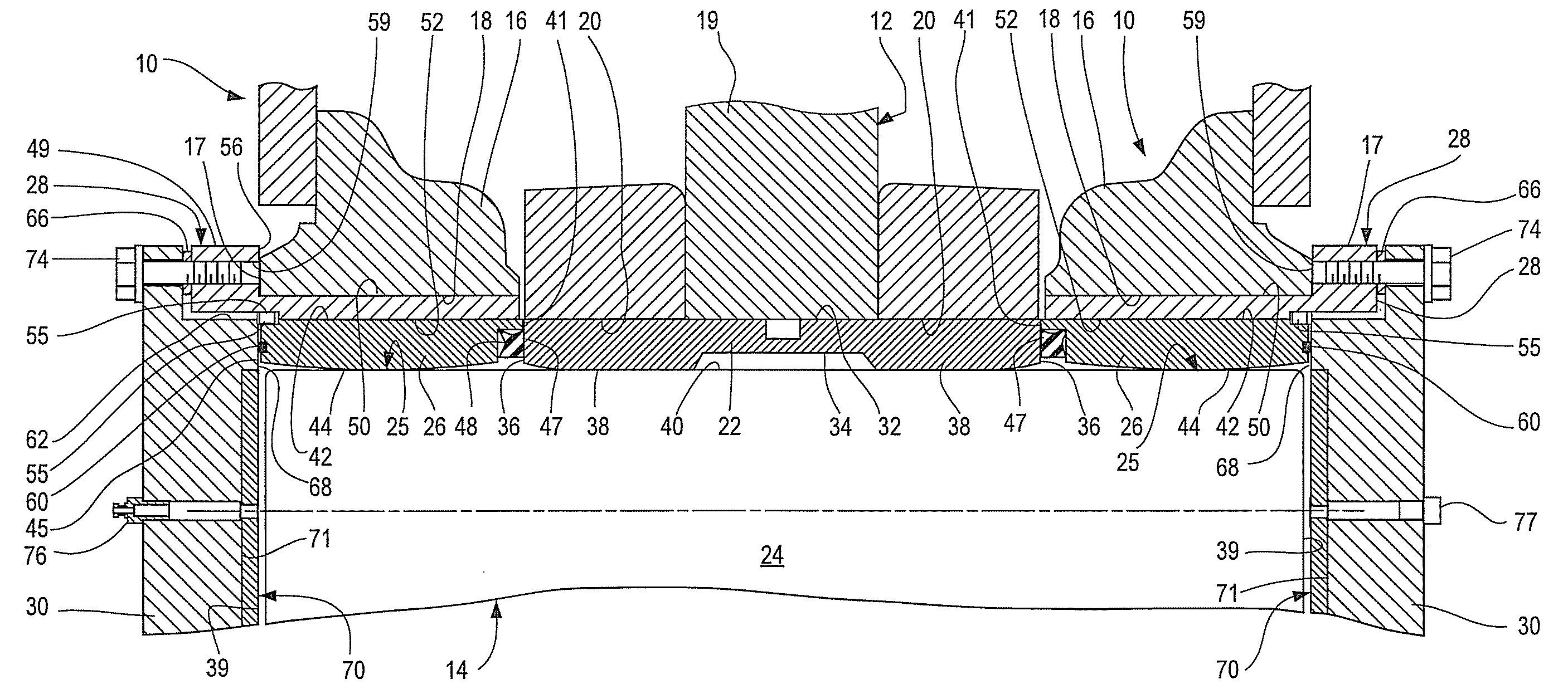
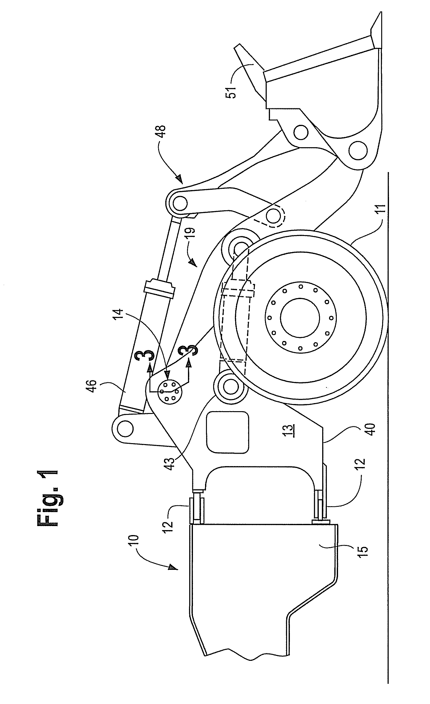
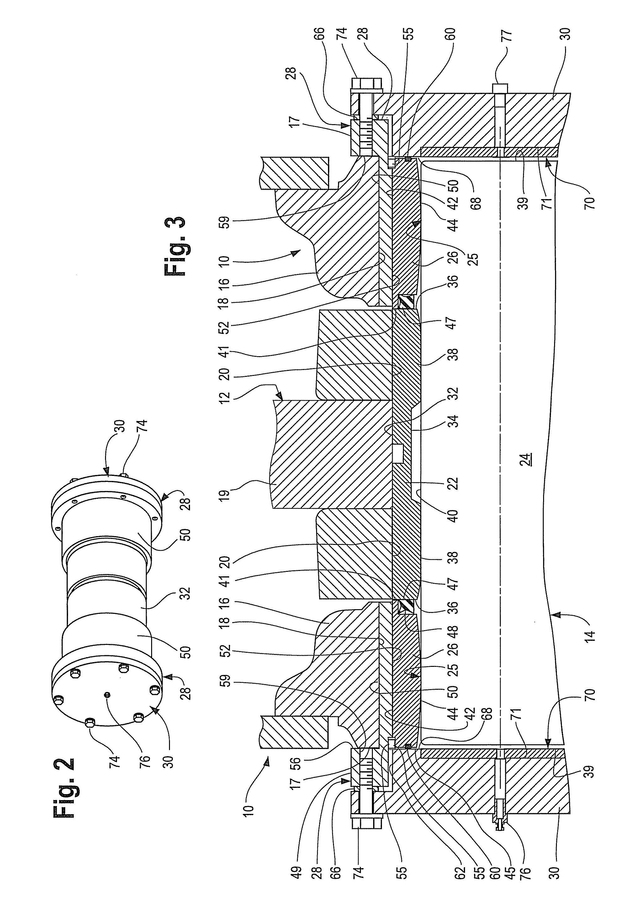
[0021]Referring now to the drawings and in particular to FIG. 1 a wheel loader is shown generally with reference 10. It should be understood, however, that many other types of equipment such as backhoes, excavators, material handlers and the like that include pivotal linkage arrangements can utilize the floating pin joint assembly described herein.
[0022]Wheel loader 10 has a structural frame with a front or non-engine end portion 13 and a rear or engine end portion 15. A plurality of ground supporting members 11 (wheels) one of which is shown, are connected to the front portion 13 and the rear portion 15 of the structural frame through axles, drive shafts or other components (not shown). A hitch arrangement pivotally connects the front portion 13 to the rear portion 15 by way of a pair of hinge joints 12.
[0023]The front portion 13 of the frame defines a first member, including spaced frame members or flanges 16, best seen in FIGS. 3 and 4. A second member, in the form of a lift arm ...
PUM
 Abstract
Description
Claims
Application Information
 - R&D Engineer
- R&D Manager
- IP Professional
- Industry Leading Data Capabilities
- Powerful AI technology
- Patent DNA Extraction
Browse by: Latest US Patents, China's latest patents, Technical Efficacy Thesaurus, Application Domain, Technology Topic, Popular Technical Reports.
© 2024 PatSnap. All rights reserved.Legal|Privacy policy|Modern Slavery Act Transparency Statement|Sitemap|About US| Contact US: help@patsnap.com