Fusible Link Unit with Hinge Section

a technology of hinge section and fusible link unit, which is applied in the direction of incorrect coupling prevention, coupling device details, coupling device connection, etc., can solve the problems of deformation of the unit, the thickness of the busbar itself needs to be thick, and the hinge section is subject to damage, so as to reduce the manufacturing cost of the mold, prevent abnormal noise of the same, and improve the resistance to vibration of the fusible link unit

Active Publication Date: 2009-04-30
YAZAKI CORP
View PDF6 Cites 20 Cited by
  • Summary
  • Abstract
  • Description
  • Claims
  • Application Information

AI Technical Summary

Benefits of technology

[0018]The distance between the two bodies can be properly set by the inner bottom surface of the recessed guide and top surface of the projected guide abutting on each other. The band plate section of the hinge section is not deformed unnecessarily. Moreover, the engagement units provided for the two bodies are therefore engaged with each other by causing the inner bottom surface of the recessed guide and the top surface of the projected guide to abut on each other and then further bending the bodies. Accordingly, it is possible to obtain an engagement without rattling using elasticity of the bodies. This can improve the resistance to vibration of the fusible link unit mounted on a battery and prevent abnormal noise of the same. Moreover, dimensional fitting tolerance of the engaging units does not need to be strictly set, thus reducing manufacturing cost of a mold. Moreover, the pairs of recessed and projected guides are arranged along the bending sections in the vertical direction. The interval between the two bodies is properly controlled at each vertical position of the recessed and projected guides. This increases workability at engaging the engagement units. Furthermore, when the engagement units are engaged with each other, the place where the recessed and projected guides abut on each other serves as a fulcrum, and tension is applied to the hinge section. This prevents deformation of the band plate section.

Problems solved by technology

Because of the variations in positional relationship between the two bodies, the unit cannot be connected to the other connector for wire length of the other connector is insufficient, unnecessary stress applied to the connecting section may cause deformation of the unit, or degradation in water proof or wire detachment of the other connector may be caused.
When the fusible link unit mounted on a vehicle is exposed to vibration, stress and fatigue are concentrated on the hinge section, and the hinge section is subject to damage.
Accordingly, the plate thickness of the busbar itself therefore needs to be thick, and the fusible link unit therefore cannot be applied to a low current fuse.

Method used


Image

  • Fusible Link Unit with Hinge Section
  • Fusible Link Unit with Hinge Section
  • Fusible Link Unit with Hinge Section

Examples


Embodiment Construction

[0034]Hereinafter, a description is given of an embodiment of the present invention with reference to the drawings.

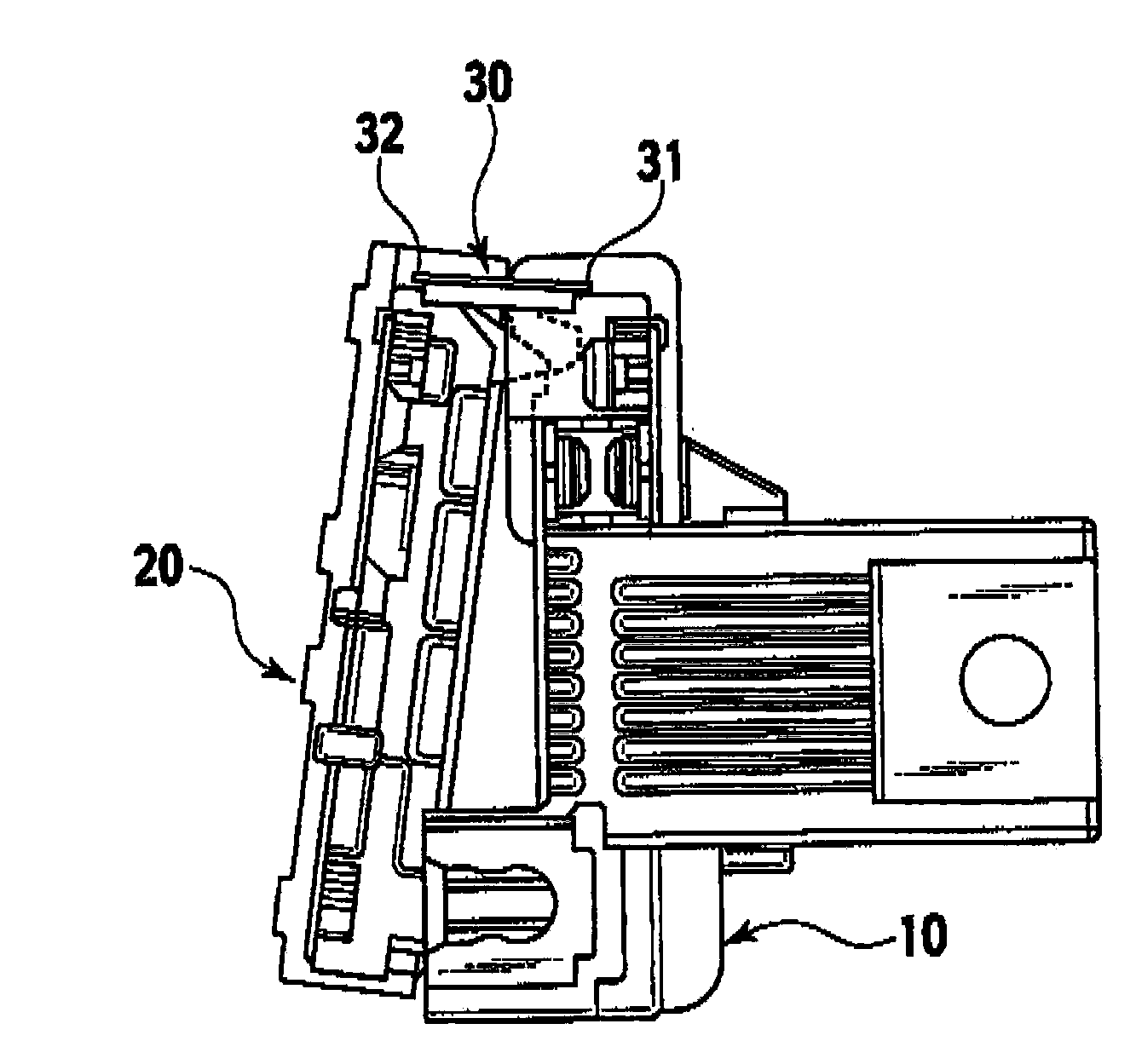
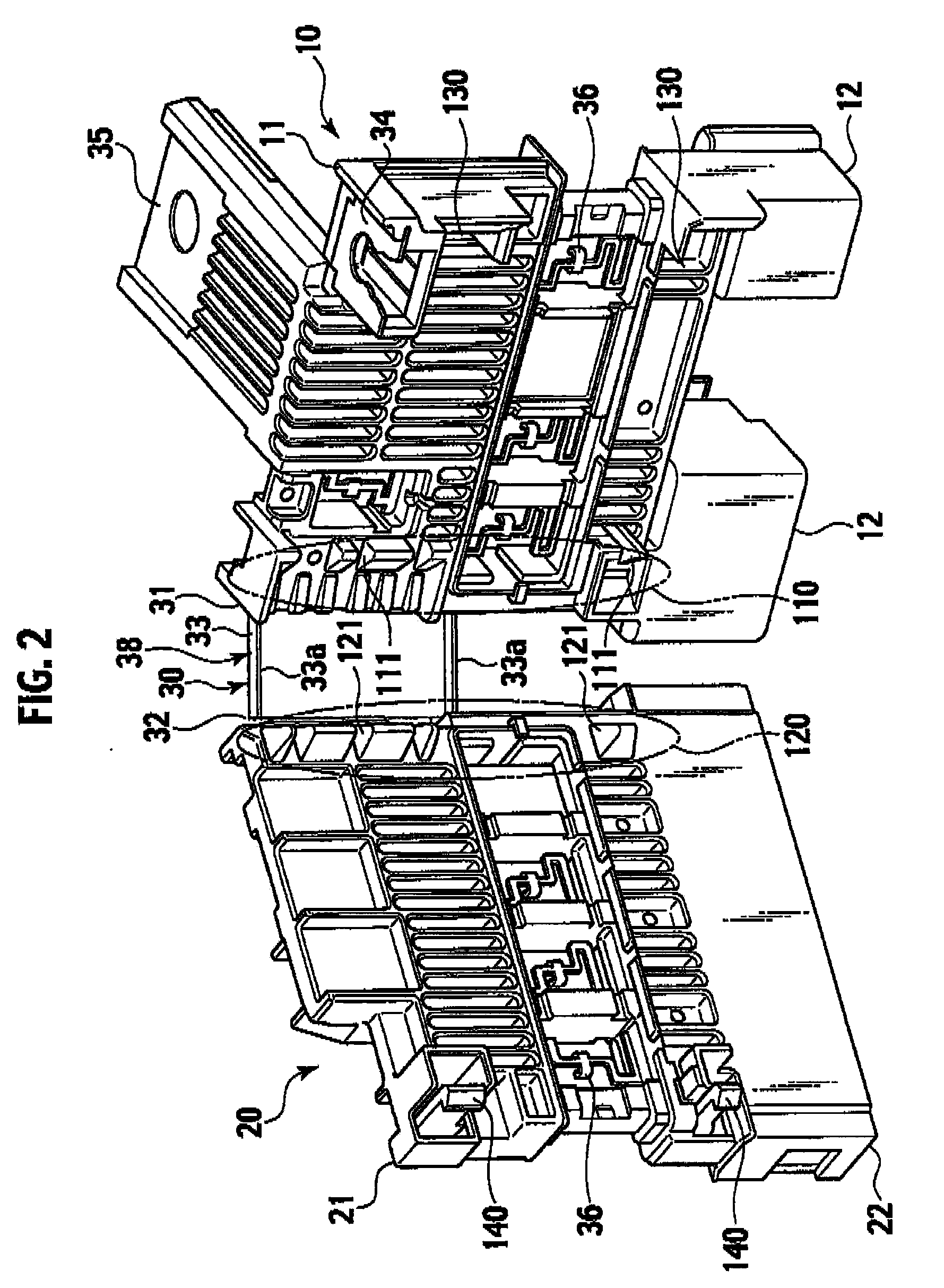
[0035]A fusible link unit shown in FIGS. 2 to 10 includes; a busbar 30; resin housings 11 and 21 assembled to necessary part of the busbar 30 by insert molding; and a resin cover covering exposed part of the busbar 30 (not shown).

[0036]The busbar 30 is fabricated by pressing a conductive metal plate. A hinge section 38 including bending sections 31 and 32 at both side edges of a band plate section 33 is provided at the center of the busbar 30. Two fuse circuit constituting plate sections (not shown) are integrally provided on both sides of the hinge section 38 to be linked thereto. These two fuse circuit constituting plate sections are pivoted at the bending sections 31 and 32 in a same direction in a bending process to be placed in parallel at a distance equal to the width of the band plate section 33.

[0037]At an upper end of one of the fuse circuit constituting plate ...


PUM


Abstract

A hinge section including bending sections at both side edges of a band plate section is provided in center of a busbar. On both sides of the hinge section, two fuse circuit constituting plate sections are integrally formed to be linked thereto. Two resin housings are assembled by insert molding to the respective fuse circuit constituting plate sections, thus forming two bodies. The two bodies are pivoted in the same direction at the bending sections, and engagement units are locked, thus constituting a fusible link unit having a U-shaped plan view. The two bodies are engaged with each other in vicinity areas of the hinge section in the opposed surfaces of the opposed resin housing when the two bodies are pivoted. The fusible link unit also includes recessed and projected guides guiding the two resin housings to proper positions.

Description

BACKGROUND OF THE INVENTION[0001]1. Field of the Invention[0002]The present invention relates to a fusible link unit which is directly mounted on a battery of a vehicle and supplies power through a plurality of fuses (a fusible section) to each load. Specifically, the present invention relates to a fusible link unit which is fabricated in a flat shape by performing insert-molding of resin housings with a busbar being attached to a mold, the busbar including a fuse circuit constituting section, and is then bent according to a form of attachment to the battery or the like into a stereoscopic block shape.[0003]2. Description of the Related Art[0004]As such a type of fusible link units, fusible link units described in Patent Publications 1 and 2 are known.[0005]The fusible link unit described in Patent Publication 1 includes a bendable hinge section 533 in the center of a busbar 530 as shown in FIG. 1. Fuse circuit constituting plate sections (not shown) are provided on both sides of th...

Claims


Application Information

Patent Timeline
Patent Type & Authority Applications(United States)
IPC IPC(8): H01R13/64H01H85/12H01H85/20
CPCH01H85/044H01H2085/0555H01H2085/025
Inventor MATSUMOTO, YUSUKEOHASHI, NORIHIRO
Owner YAZAKI CORP
Why Eureka
Try Eureka