Electrical connector

Active Publication Date: 2009-04-30
LOTES
View PDF4 Cites 27 Cited by
  • Summary
  • Abstract
  • Description
  • Claims
  • Application Information

AI Technical Summary

Benefits of technology

[0009]The advantages of the present invention lie in that the shielding layers are mounted on the insulating body and the insulating layers are mounted on the shielding layers, thereby reducing EMI between terminals and preventing the terminals from contacting the shielding layers

Problems solved by technology

However, how to protect the transmission of data from EMI is an issue in the development of high terminal density technology.
However, because the metal layer is only disposed on the surface of the insulating body, the influen

Method used


Image

  • Electrical connector
  • Electrical connector
  • Electrical connector

Examples


Embodiment Construction

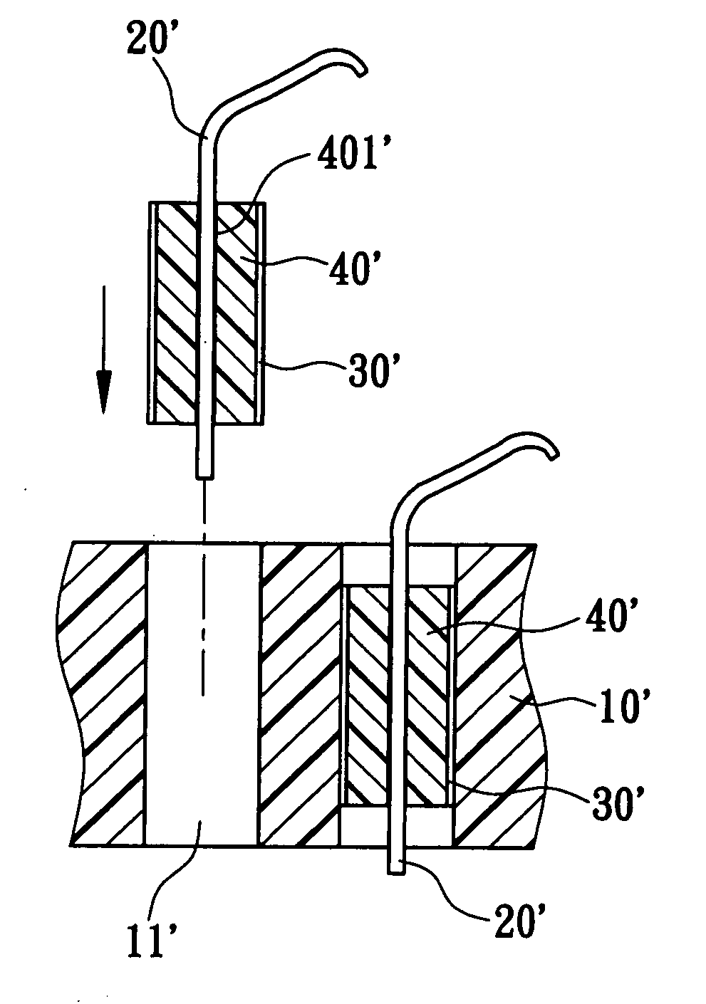
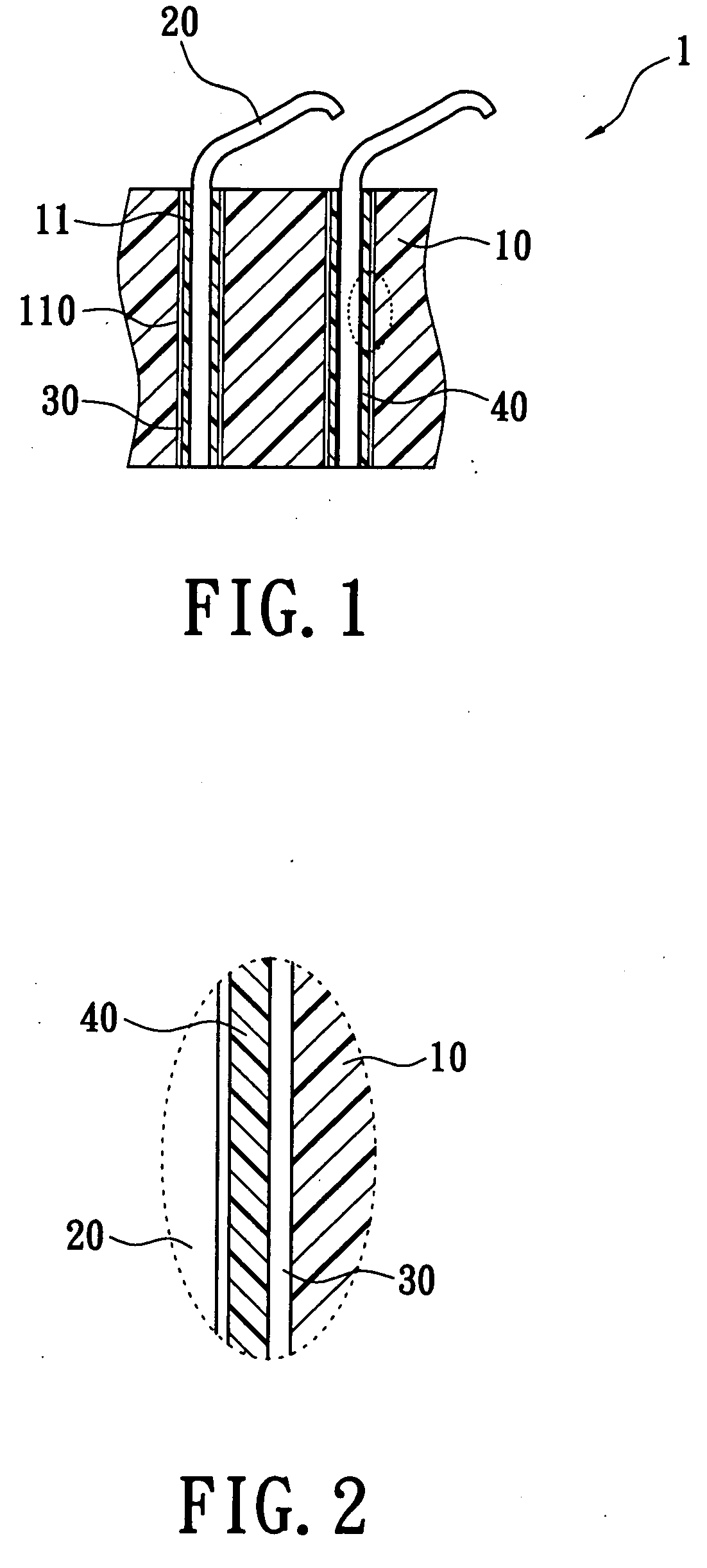
[0016]Please refer to FIG. 1 and FIG. 2, in which the present invention of an electrical connector 1 is shown. The electrical connector 1 includes an insulating body 10 and a plurality of terminals 20. The insulating body 10 has a plurality of terminal-receiving holes 11 and the terminals 20 are set in the terminal-receiving holes 11. A plurality of shielding layers 30 are attached to an inner wall 110 of each of the terminal-receiving holes 11. The shielding layers 30 can prevent crosstalk that occurs due to the near gap of the terminals 20. A plurality of insulating layers 40 that are covered with and attached to the shielding layers 30 prevent the terminals 20 from contacting the shielding layers 30.

[0017]The shielding layers 30 that are disposed around the terminal-receiving holes 11 and correspond to the shape of the terminal-receiving holes 11 can be metal housings. The shielding layers 30 also can be metal films plated to the inner wall 110 of the terminal-receiving holes 11 ...


PUM


Abstract

An electrical connector includes an insulating body, a plurality of terminals, a plurality of shielding layers, and a plurality of insulating layers. The insulating body has a plurality of terminal-receiving holes. The shielding layers are mounted on the terminal-receiving holes. The insulating layers are mounted on the shielding layers, and the terminals are disposed in the terminal-receiving holes. Thereby, the insulating layers prevent EMI between terminals and ensure the terminals do not contact the shielding layers.

Description

CROSS REFERENCE TO RELATED APPLICATION[0001]This application is a continuation-in-part of U.S. application Ser. No. 11 / 832,231, filed on 1 Aug. 2007 and entitled “electrical connector”, now pending.BACKGROUND OF THE INVENTION[0002]1. Field of the Invention[0003]The present invention relates to an electrical connector, and in particular to an electrical connector having a shielding layer for preventing EMI (Electromagnetic Interference).[0004]2. Description of the Prior Art[0005]As computer and digital technology have advanced, the need for products to transmit data faster has been constant. To obtain the high data transmission speed, there are a number of electrical connectors with high terminal density available on the market such as LGA (Land Grid Array) connector. However, how to protect the transmission of data from EMI is an issue in the development of high terminal density technology. The ordinary method for preventing EMI is to install a layer of a metal or set a plated film ...

Claims


Application Information

Patent Timeline
IPC IPC(8): H01R13/648
CPCH01R13/6599H01R13/2442
Inventor JU, TED
Owner LOTES
Why Eureka
Try Eureka