Display interface device and data transmission method thereof

a technology of data transmission and display interface, which is applied in the field of display devices, can solve the problems of data loss, epi interface of the related art has a difficulty in largely increasing the length of packet transmission units, and the transmission speed of epi increases, so as to increase the efficiency of display information transmission and reduce power consumption and emi

Active Publication Date: 2018-07-05
LG DISPLAY CO LTD
View PDF0 Cites 11 Cited by
  • Summary
  • Abstract
  • Description
  • Claims
  • Application Information

AI Technical Summary

Benefits of technology

[0011]The present disclosure provides a display interface device and a data transmission method thereof which can increase display information transmission efficiency and reduce power consumption and EMI.

Problems solved by technology

However, when a length of the transmission unit of the EPI packet increases infinitely, internal clock timing cannot be adjusted because DLL synchronization becomes difficult due to a clock skew problem, resulting in data loss.
Accordingly, the EPI interface of the related art has a difficulty in largely increasing the length of the packet transmission unit.
In addition, for example, each EPI packet in the transmission unit of 24 UIs further includes the 4-bit delimiter in addition to the 20-bit image data and thus requires an overhead operation of 120% (=24 / 20), and thus the transmission speed of the EPI increases and power consumption and EMI also increase in proportion thereto.
Furthermore, when multiple EPI packets in the transmission unit of 24 UIs are transmitted through multiple channels CH1 and CH2, as illustrated in FIG. 2, a display interface device of the related art redundantly transmits clock edge information through the multiple channels CH1 and CH2 at the same timing, resulting in transmission efficiency deterioration and EMI increase.

Method used


Image

  • Display interface device and data transmission method thereof
  • Display interface device and data transmission method thereof
  • Display interface device and data transmission method thereof

Examples


Embodiment Construction

[0031]Reference will now be made in detail to the aspects of the present disclosure, examples of which are illustrated in the accompanying drawings. Wherever possible, the same reference numbers will be used throughout the drawings to refer to the same or like parts.

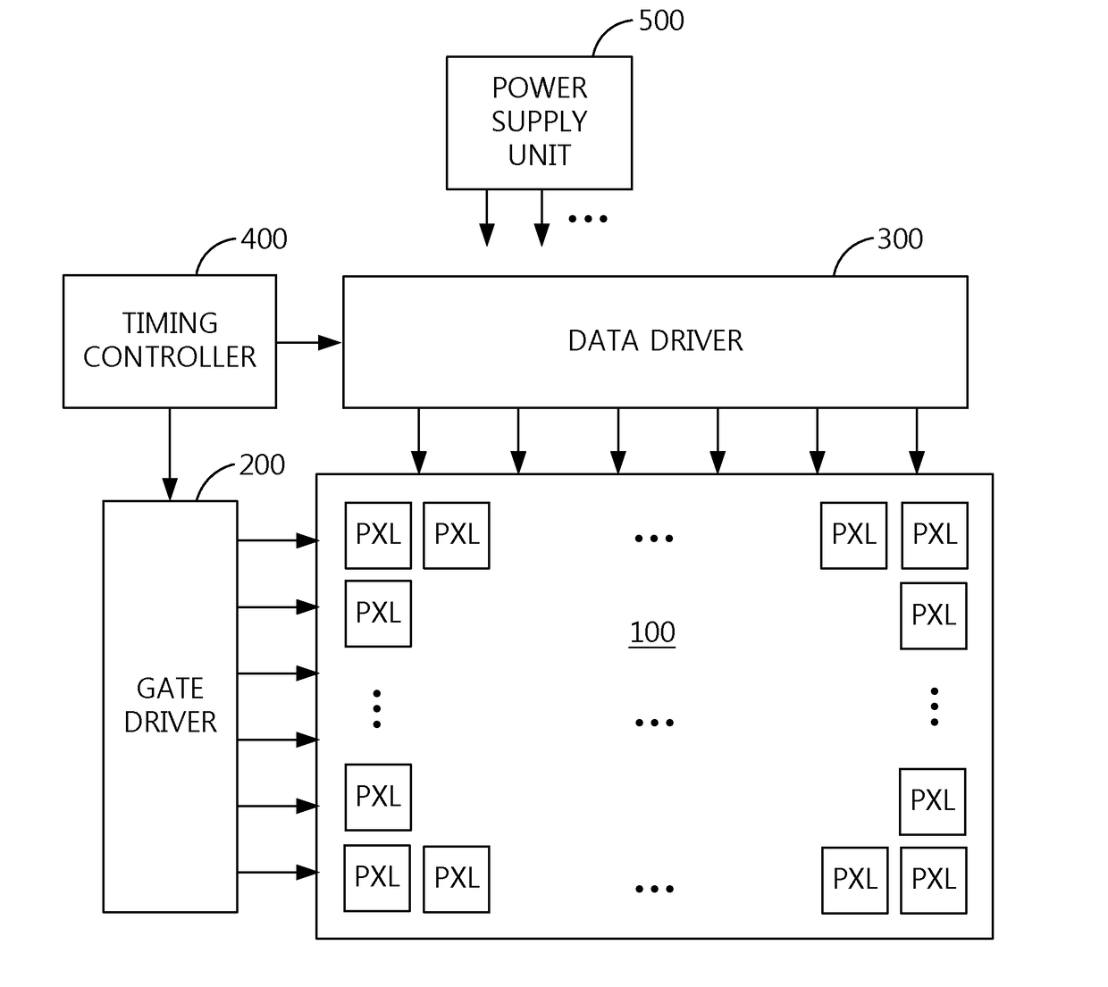
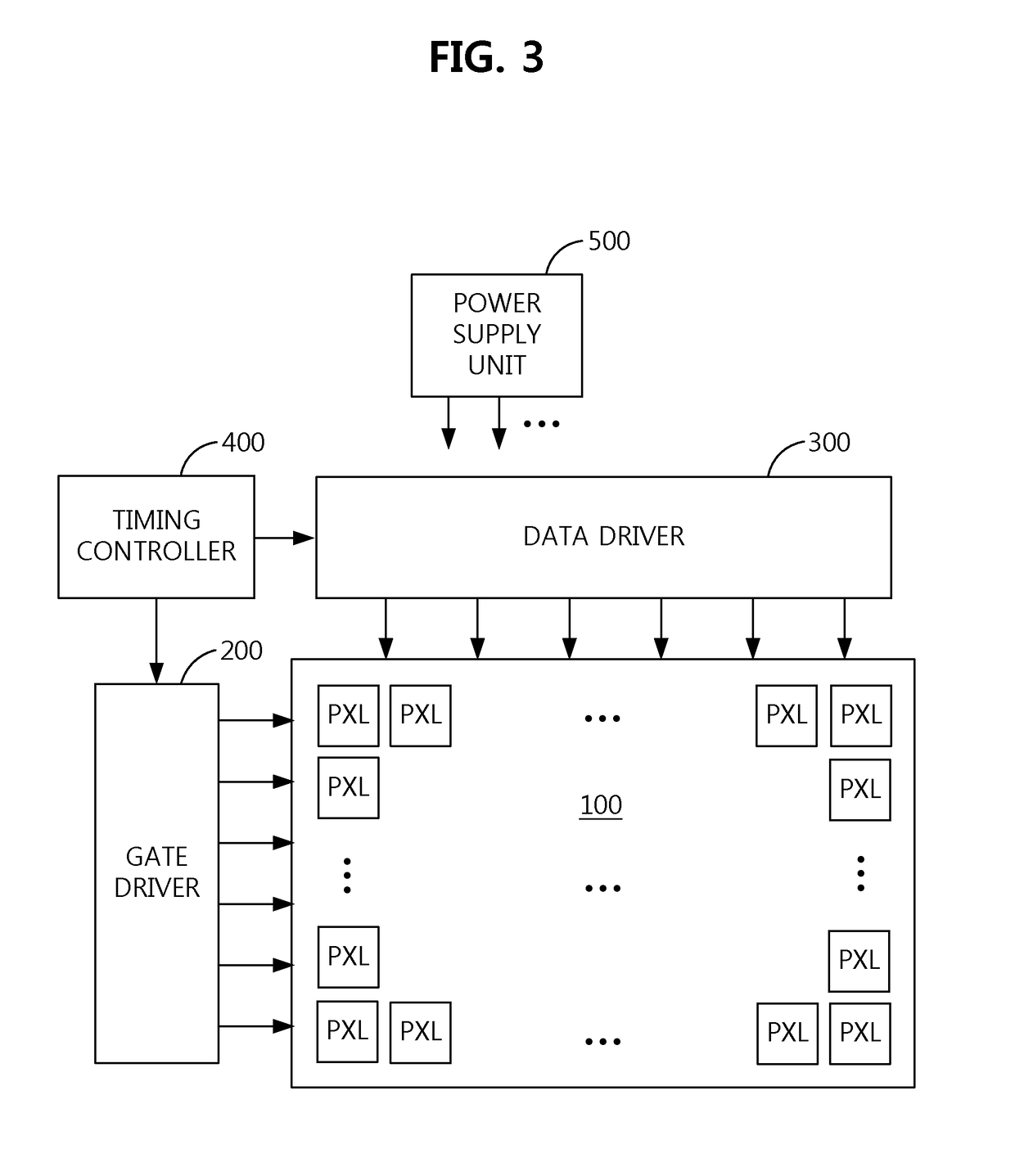
[0032]FIG. 3 is a block diagram schematically illustrating a configuration of a display device according to an aspect of the present disclosure and FIG. 4 illustrates a connection structure of a timing controller and multiple data driving ICs in a display device according to an aspect of the present disclosure.

[0033]Referring to FIG. 3, the display device includes a panel 100, a gate driver 200, a data driver 300, a timing controller (TCON) 400 and a power supply unit 500.

[0034]The panel 100 displays images through a pixel array in which pixels PXL are arranged in a matrix form. The unit pixel of the pixel array may be composed of at least three subpixels W / R / G, B / W / R, G / B / W, R / G / B or W / R / G / B which can express white thro...


PUM


Abstract

The present disclosure relates to a display interface device which can increase display information transmission efficiency and reduce power consumption and EMI, in which a transmission part transmits clock edge information included in a data packet of each channel at a different timing from clock edge information included in data packets of other channels. A reception part detects a clock edge of each channel from the data packet transmitted through each channel, generates an internal clock signal of each channel, synchronized with the detected clock edge, corrects a delay of each channel depending on a result of a logical operation performed on a delayed clock edge of a channel and a clock edge of another channel to further generate an internal clock signal of each channel, and restores the display information from the data packet of each channel using the internal clock signal of each channel.

Description

CROSS-REFERENCE TO RELATED APPLICATION[0001]This application claims the benefit of Republic of Korea Patent Application No. 10-2016-0184083, filed on Dec. 30, 2016, which is hereby incorporated by reference in its entirety.BACKGROUNDField of the Disclosure[0002]The present disclosure relates to a display device, and more particularly, to a display interface device and a data transmission method thereof which can increase display information transmission efficiency and reduce power consumption and electromagnetic interference (EMI).Description of the Background[0003]There are liquid crystal displays (LCDs) using liquid crystal, organic light-emitting diode (OLED) displays using OLEDs and electrophoretic displays (EPDs) using electrophoretic particles as recent display devices for displaying images using digital data.[0004]A display device includes a panel that displays images through a pixel array, a panel driver for driving the panel, and a timing controller for controlling the pane...

Claims


Application Information

Patent Timeline
Patent Type & Authority Applications(United States)
IPC IPC(8): G09G5/00G09G3/20
CPCG09G5/008G09G3/2096G09G2310/0243G09G2310/0297G09G2330/021G09G2330/06G09G2370/045G09G5/006G09G3/2092G09G3/3685G09G2370/08G09G2370/10G09G5/003
Inventor PARK, DONG-WONKIM, JANG-HWANPARK, JONG-MINLEE, JOON- HEEKWON, YONG-CHUL
Owner LG DISPLAY CO LTD
Why Eureka
Try Eureka