

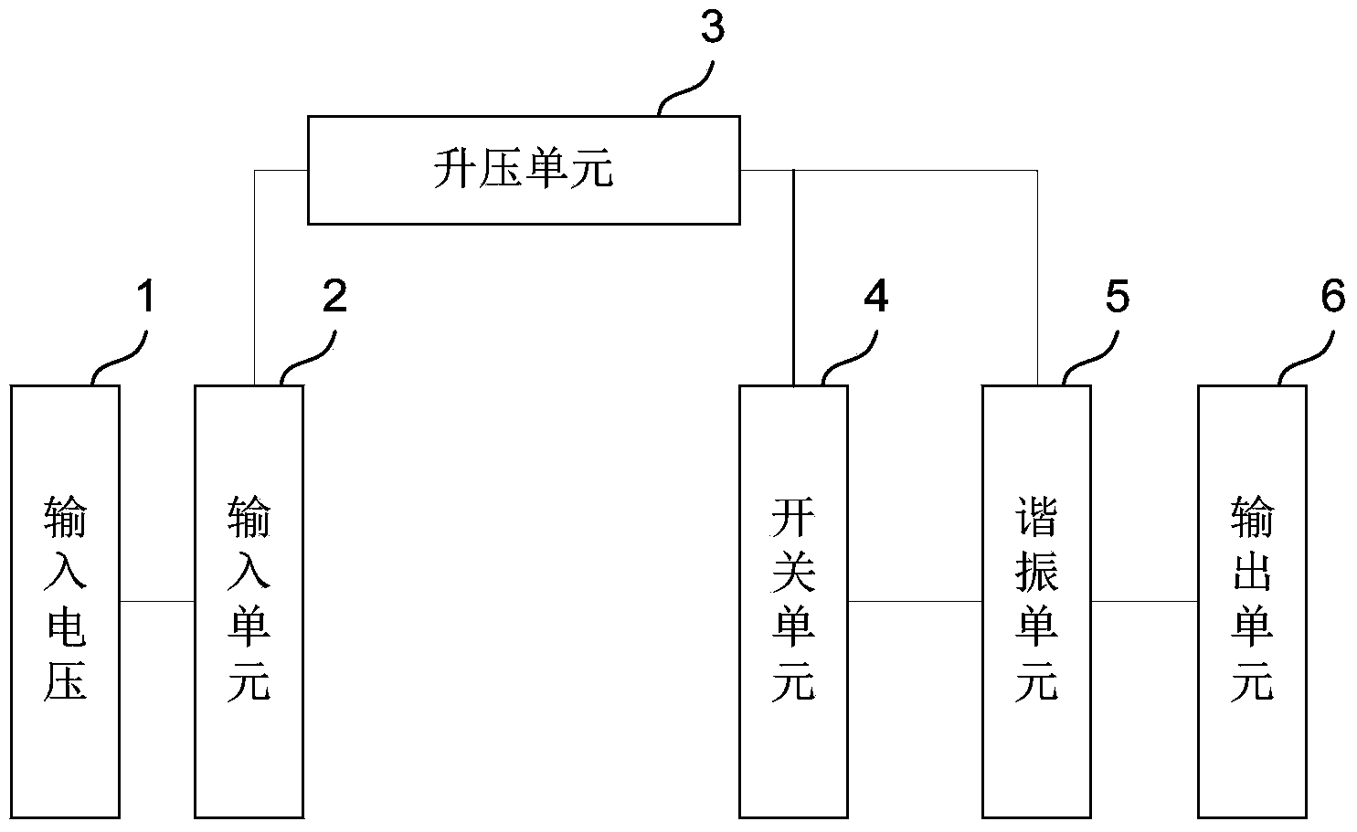
Soft switching Boost topology circuit
A topology circuit and soft switching technology, applied in electrical components, regulating electrical variables, high-efficiency power electronic conversion, etc., can solve problems such as low conversion efficiency and electromagnetic interference, achieve simple control methods, reduce EMI, and improve energy conversion. The effect of efficiency
- Summary
- Abstract
- Description
- Claims
- Application Information
AI Technical Summary
Problems solved by technology
Method used
Image

Examples
Embodiment 1
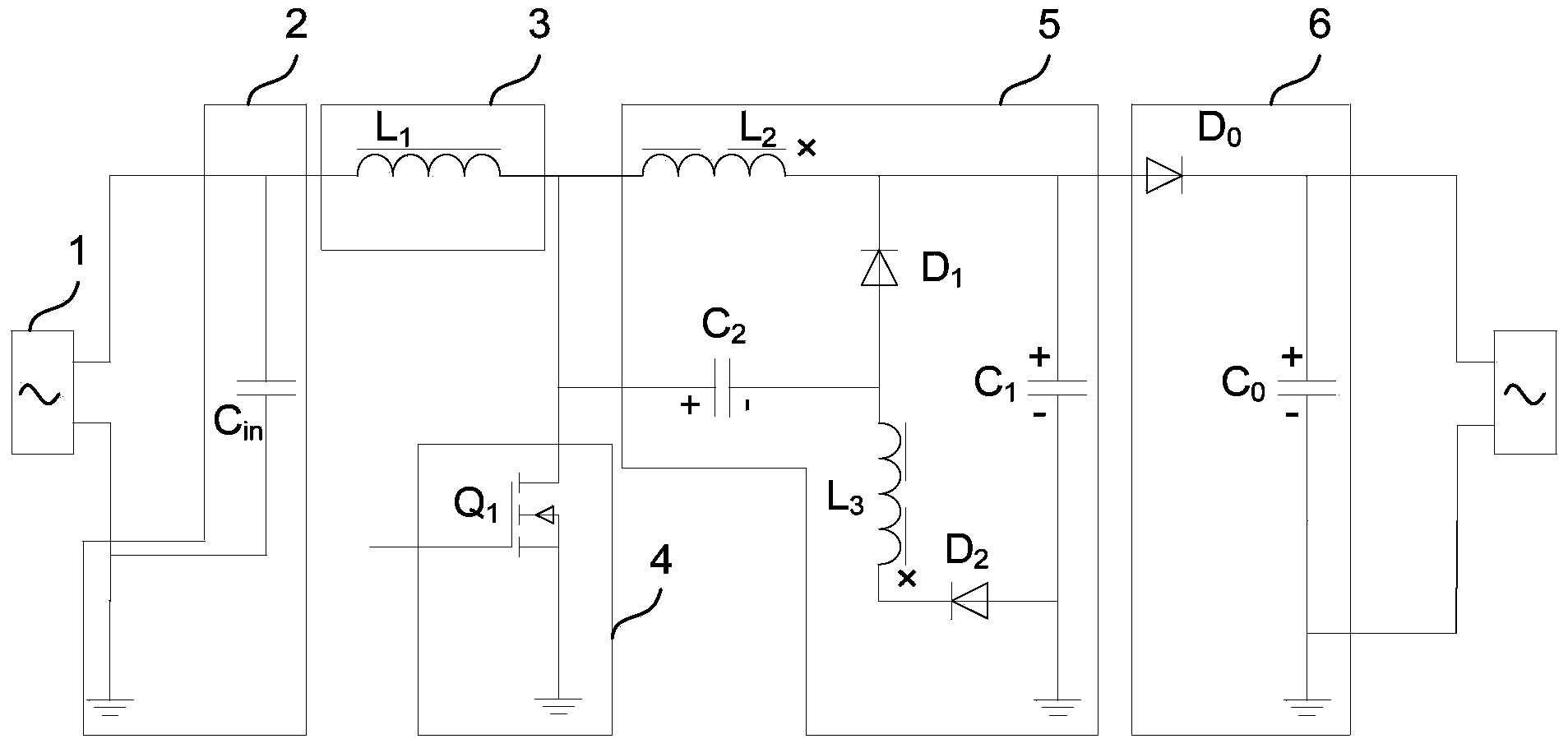
[0027] Please refer to figure 2 , shows a structural diagram of a soft-switching Boost topology circuit in a specific embodiment of the present invention, the circuit includes a capacitor C in , inductance L 1 , MOS tube Q 1 , Diode D 0 and capacitance C 0 , the diode D 0 The anode is connected to the resonance unit 5, and the diode D 0 cathode connected to the capacitor C 0 positive terminal, the capacitor C 0 The negative terminal of the ground, the capacitor C in Both ends of the input voltage 1 are connected, while the capacitor C in The positive terminal of the inductor L is connected 1 at one end, the inductance L 1 The other end is connected to the MOS transistor Q 1 drain; wherein the resonant unit 5 includes a coupled inductor L 2 with L 3 , capacitance C 1 , capacitance C 2 , Diode D 1 and diode D 2 , the coupled inductance L 2 Nominal terminal with the inductance L 1 The other end of the capacitor C 2 The anode of the MOS tube is connected to th...
Embodiment 2
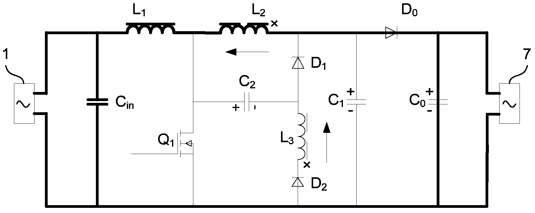
[0038] In addition, the present invention also provides another specific embodiment of the soft-switching Boost topology circuit, please refer to Figure 4 , shows a structure diagram of a soft-switching Boost topology circuit in another specific embodiment of the present invention, the difference from the first embodiment is that each element in the resonance unit 5 is different from the components outside the resonance unit 5 The connection relationship of other electronic components is slightly different, specifically: the resonant unit 5 includes a coupling inductor L 2 with L 3 , capacitance C 1 , capacitance C 2 , Diode D 1 and diode D 2 , the coupled inductance L 2 Nominal terminal with the capacitor C 2 The anode of the MOS tube is connected to the drain, and the coupled inductor L 2 terminal with the same name as the inductor L 1 The other end of the diode D 1 cathode, the capacitor C 1 the anode of the diode D 0 connected to the anode of the capacitor C 2...
PUM
 Abstract
Description
Claims
Application Information