
Method and apparatus for providing a dual-loop phase lock loop

Active Publication Date: 2009-04-30
AVAGO TECH INT SALES PTE LTD
View PDF8 Cites 9 Cited by
  • Summary
  • Abstract
  • Description
  • Claims
  • Application Information

AI Technical Summary

Benefits of technology

[0010]A method and apparatus for providing a dual-loop phase lock loop (PLL) for a radio-frequency (RF) receiver is provided. The dual-loop PLL includes coarse tuning circuitry and fine tuning circuitry. The coarse turning circuitry and fine tuning circuitry may be arranged in parallel. Both of the coarse tuning circuitry and fine tuning circuitry provide respective tuning signals to a voltage-controlled oscillator (VCO), such as a varactor-tuned VCO. The coarse tuning circuitry and the fine tuning circuitry may provide the respective tuning signals to the VCO simultaneously. In this manner, the dual-loop PLL may provide a highly-integratable solution having a wide frequency lock range and low phase noise.

Problems solved by technology

In particular, a conventional PLL circuit may use capacitor-based integrator and / or operational amplifiers that do not facilitate a single or multiple integrated circuit solution because capacitors and resistors used by the capacitor-based integrator and / or the operational amplifiers are located externally from the integrated circuit in which the PLL circuit is formed.
Furthermore, conventional PLLs utilize two-stage search and lock strategies that are time and power consuming.
Such recalibration occurs the conventional PLLs are powered on for a prolonged time period, which may cause changes in temperature and / or other conditions that effect calibration.
The re-calibration can be very problematic for RF receivers because the time and power spent on recalibration cannot be used for processing incoming signals.

Method used


Image

  • Method and apparatus for providing a dual-loop phase lock loop
  • Method and apparatus for providing a dual-loop phase lock loop
  • Method and apparatus for providing a dual-loop phase lock loop

Examples


Embodiment Construction

[0016]In the following detailed description, numerous specific details are set forth in order to provide a thorough understanding of exemplary embodiments or other examples described herein. However, it will be understood that these embodiments and examples may be practiced without the specific details. In other instances, well-known methods, procedures, components and circuits have not been described in detail, so as not to obscure the following description. Further, the embodiments disclosed are for exemplary purposes only and other embodiments may be employed in lieu of, or in combination with, the embodiments disclosed.

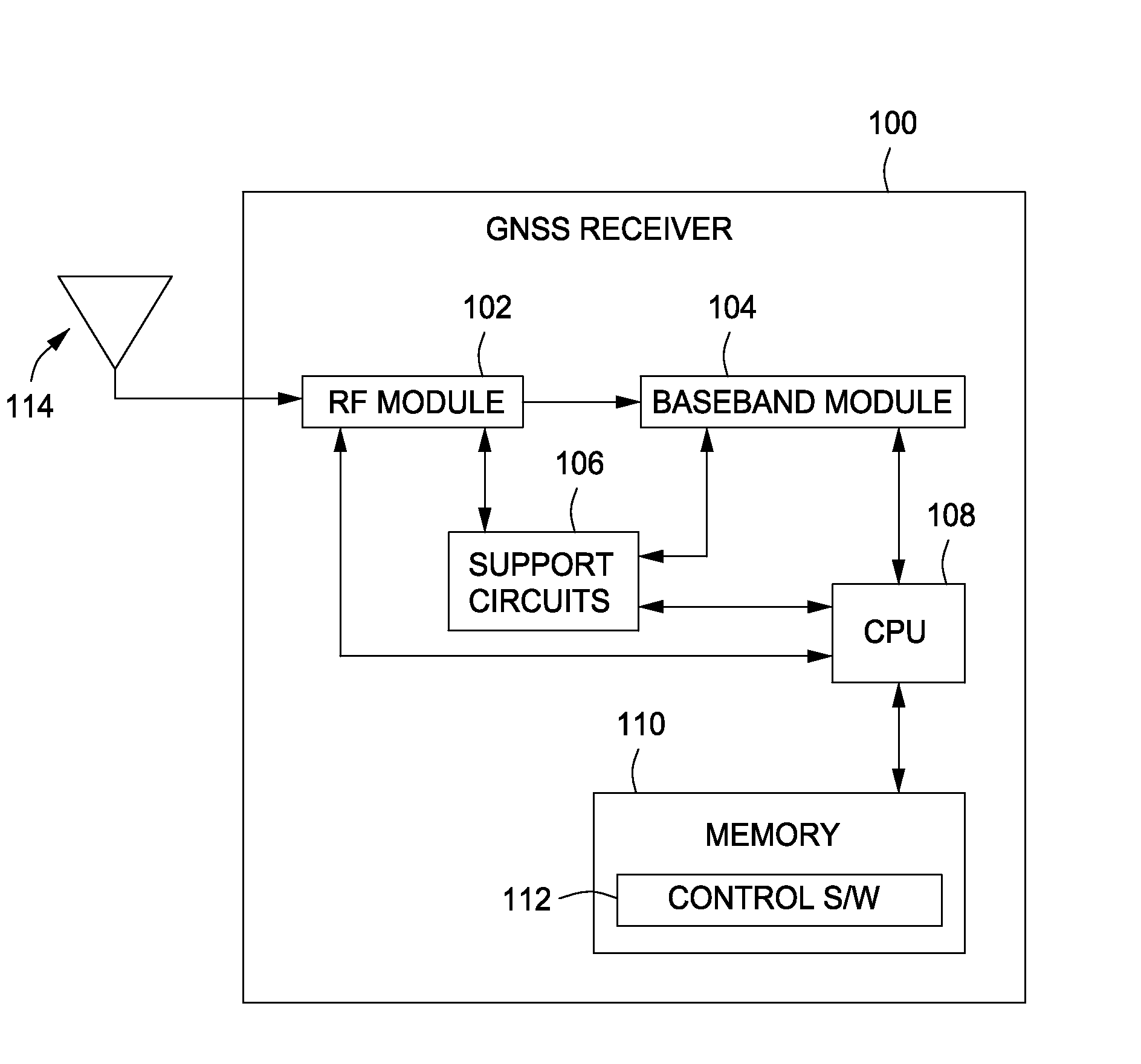
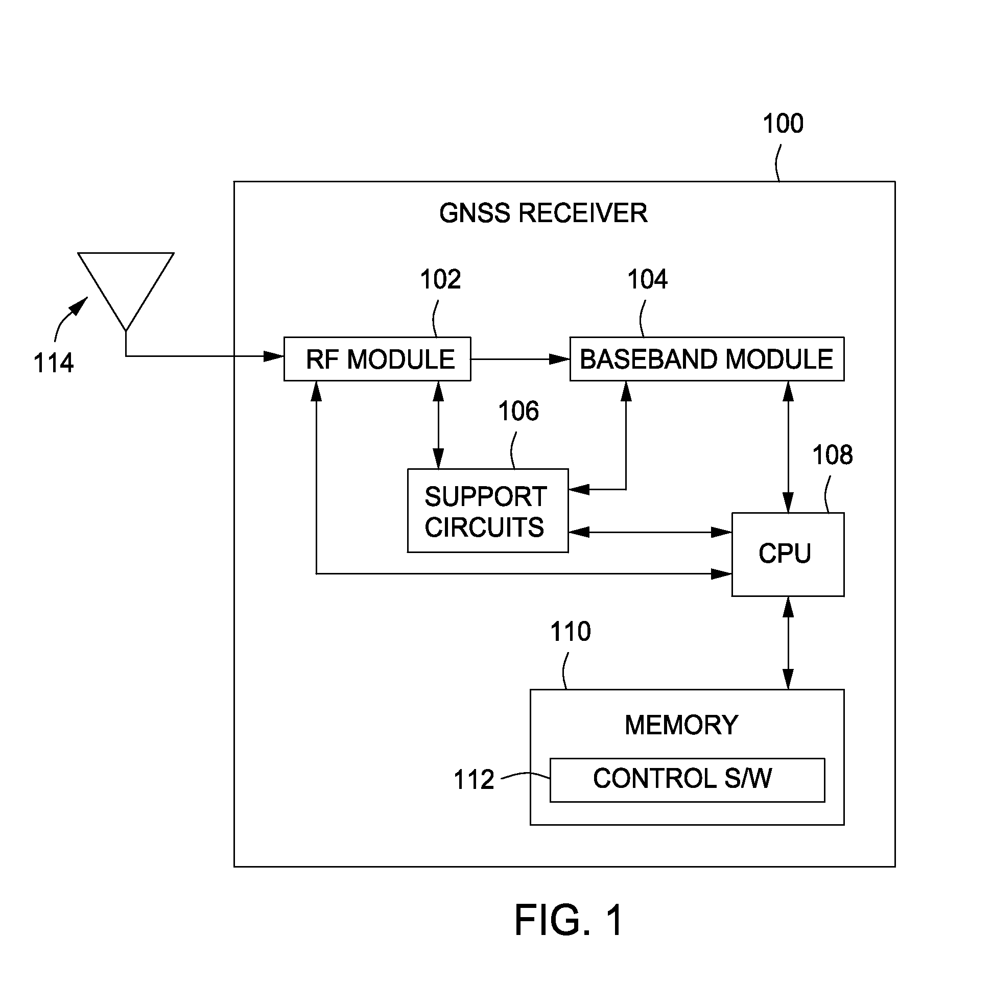
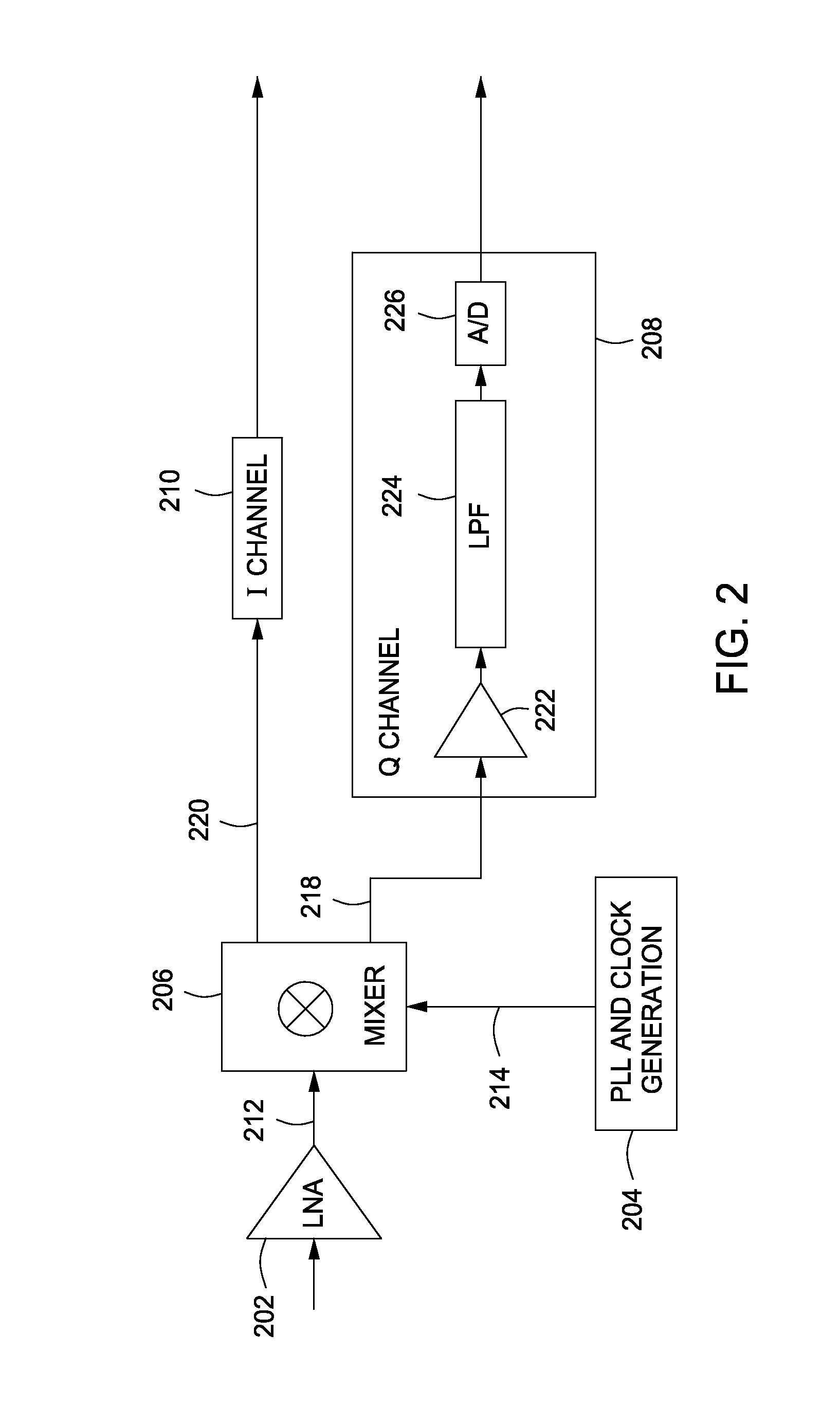
[0017]Described herein below are embodiments and other examples of a method and apparatus for providing a phase-lock loop (PLL) for a radio-frequency (RF) receiver, such as receiver adapted to process a satellite or cellular signal. These embodiments and other examples may be particularly useful for deployment in a receiver that is usable in a Global-Navigation-Sa...


PUM


Abstract

A method and apparatus for providing a dual-loop phase lock loop (PLL) for a radio-frequency (RF) receiver is provided. The dual-loop PLL may include coarse tuning circuitry and fine tuning circuitry. The coarse turning circuitry and fine tuning circuitry may be arranged in parallel. Both of the coarse tuning circuitry and fine tuning circuitry provide respective tuning signals to a voltage-controlled oscillator (e.g., a varactor tuned VCO). The coarse tuning circuitry and the fine tuning circuitry may provide the respective tuning signals simultaneously. In addition, coarse and fine tuning circuitry may be formed monolithically with other elements of the dual-loop PLL so as to provide a highly-integratable having a wide frequency lock range and high sensitivity.

Description

BACKGROUND OF THE INVENTION[0001]1. Field of the Invention[0002]The present invention relates to radio frequency (RF) communications and, more particularly, to a method and apparatus for providing a dual-loop phase lock loop in a radio-frequency (RF) receiver.[0003]2. Description of the Related Art[0004]Increasing market penetration of wireless communications or simply, wireless devices, such as cellular telephones, radios, global navigation satellite systems (GNSS) receivers / transceivers, and the like, is generally premised on reducing costs associated with deployment of such devices while maintaining or improving performance and / or adding features thereto. One way to accomplish this task is to continually improve upon the devices' components that perform electronic functions for wireless communications. For example, through continuous improvement of such components, newer generations of such wireless devices are routinely deployed in smaller packages with more processing power and...

Claims


Application Information

Patent Timeline
IPC IPC(8): H04B1/18H04B1/06
CPCH03L7/1976H03L7/107
Inventor RODAL, ERIC
Owner AVAGO TECH INT SALES PTE LTD
Learn More