

Biological information collecting device and method for controlling the same
a technology of biochemical information and collecting device, which is applied in the field of biochemical information collection device, can solve the problems of difficult to accurately set the measuring point right on the eardrum inside the acoustic foramen, and the user cannot see which direction the mirror or the probe is inserted into the acoustic foramen, so as to achieve the effect of detecting a variation in loudness and a more convenient way of detecting the variation
- Summary
- Abstract
- Description
- Claims
- Application Information
AI Technical Summary
Benefits of technology
Problems solved by technology
Method used
Image

Examples
embodiment 1
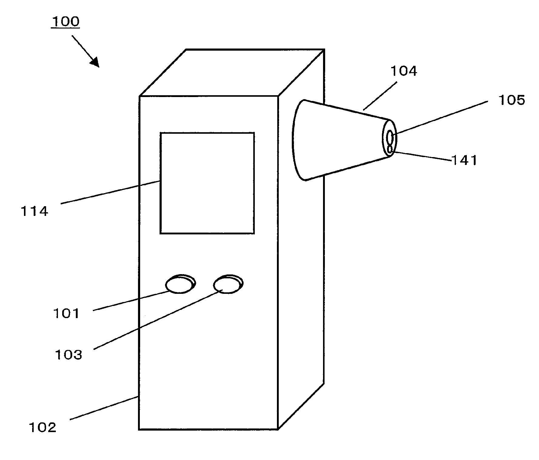
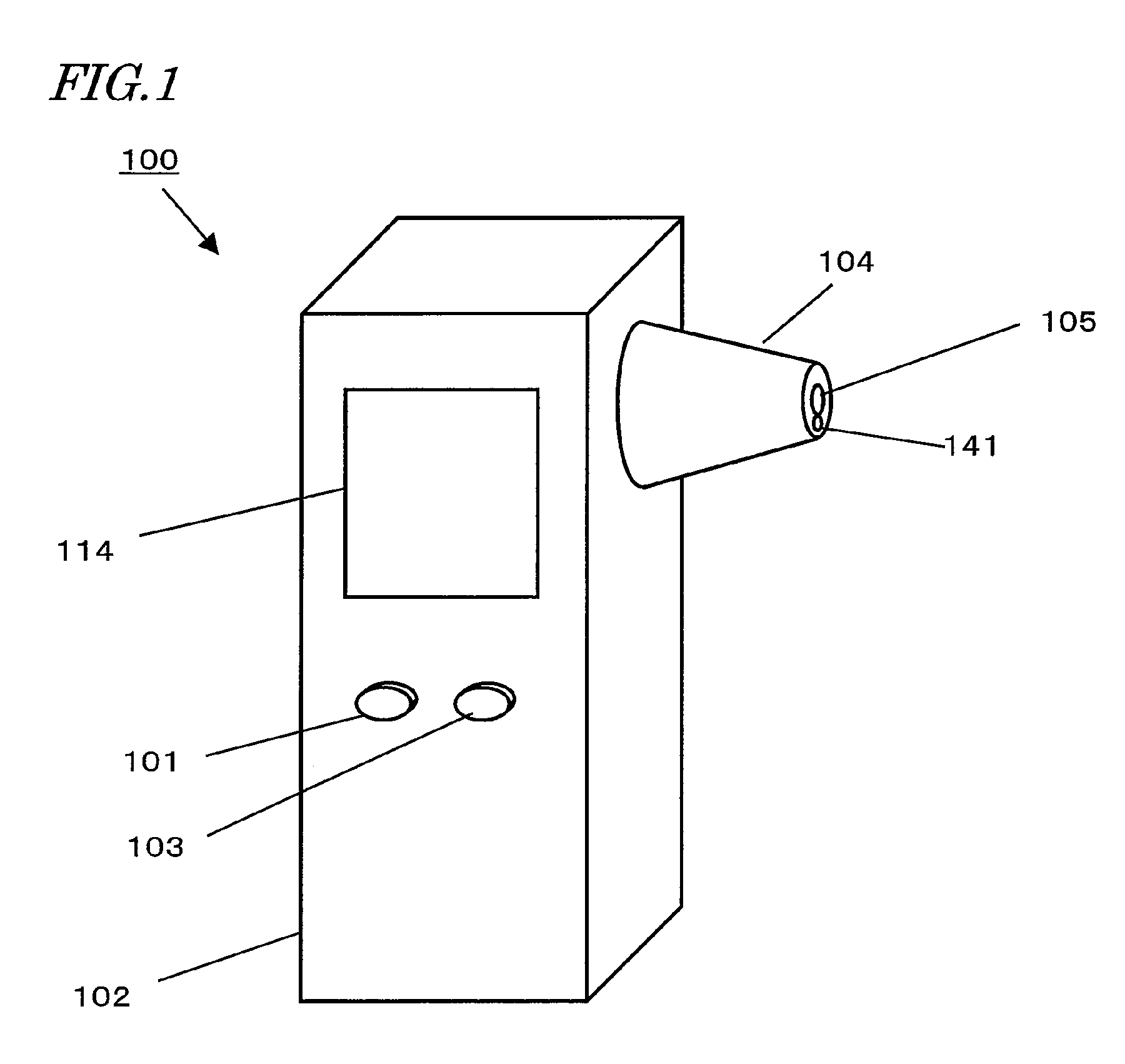
[0096]FIG. 1 is a perspective view illustrating the appearance of a biological information collecting device 100 as a first preferred embodiment of the present invention.
[0097]the Biological Information Collecting Device 100 includes a body 102 and an inserting portion 104 arranged on a side surface of the body 102. The body 102 includes a display 114 such as an LCD to show the biological constituent concentration measured, a power switch 101 to turn ON and OFF the biological information collecting device 100, and a measuring start switch 103 to start the measuring process. The inserting portion 104 includes an optical waveguide 105 for guiding the infrared radiation that has been emitted from the acoustic foramen into the biological information collecting device 100 and a first acoustic waveguide 141 for transmitting an acoustic wave from the body 102 into the acoustic foramen.
[0098]In this example, the opening of the first acoustic waveguide 141 is located at the end (or terminal)...
embodiment 2
[0138]Hereinafter, a biological information collecting device as a second preferred embodiment of the present invention will be described.
[0139]The appearance of the biological information collecting device 210 of this preferred embodiment is different from that of the first preferred embodiment described above in that the device 210 further includes a second acoustic waveguide 142. Other than that, the appearance of the second preferred embodiment is quite the same as the first preferred embodiment, and the description thereof will be omitted herein. FIG. 5 is a perspective view illustrating the appearance of the biological information collecting device 210 of the second preferred embodiment.
[0140]The inserting portion 104 includes an optical waveguide 105 for guiding the infrared radiation that has been emitted from inside the acoustic foramen into the biological information collecting device 210, a first acoustic waveguide 141 for transmitting an acoustic wave from the body 102 i...
embodiment 3
[0168]Hereinafter, a biological information collecting device as a third preferred embodiment of the present invention will be described.
[0169]The appearance of the biological information collecting device 211 of this preferred embodiment is the same as that of the biological information collecting device 210 of the second preferred embodiment described above, and the description thereof will be omitted herein.
[0170]Next, the internal configuration of the body of the biological information collecting device 211 will be described with reference to FIG. 7, which illustrates the configuration of the biological information collecting device 211 of the third preferred embodiment. The biological information collecting device 211 of this preferred embodiment further includes a frequency modulator 145 in addition to every component of the second preferred embodiment described above.
[0171]The body of the biological information collecting device 211 includes a chopper 118, an optical filter w...
PUM
 Abstract
Description
Claims
Application Information