Spinal dynamic stabilization device

a dynamic stabilization device and spine technology, applied in the field of spine dynamic stabilization device, can solve the problems of patient lower back pain and eventual non-fusion of spine, and achieve the effects of reducing complexity and time of operation, restoring height, and increasing dynamic stability between vertebra

Inactive Publication Date: 2009-04-30
IND TECH RES INST
View PDF47 Cites 96 Cited by
  • Summary
  • Abstract
  • Description
  • Claims
  • Application Information

AI Technical Summary

Benefits of technology

[0014]The invention provides a spinal dynamic stabilization device to reduce complexity and time of operation, to restore height between two adjacent vertebras, to increase dynamic stability between vertebrae, to mitigate nerve compression caused by degenerative spondylolisthesis and spinal stenosis of the spinal canal, and to ease a patient's pain.
[0016]The connecting member, the supporting member, and the anchoring member relatively move and comprise at least a movable connecting point for increasing dynamic stability.

Problems solved by technology

For stenosis, central nerves or nerve roots in the spinal canal are compressed, resulting in lower back pain for patient.
However, spine non-fusion may eventually develop due to limited patient movement degenerating adjacent discs due to overweight pressure.

Method used


Image

  • Spinal dynamic stabilization device
  • Spinal dynamic stabilization device
  • Spinal dynamic stabilization device

Examples


first embodiment

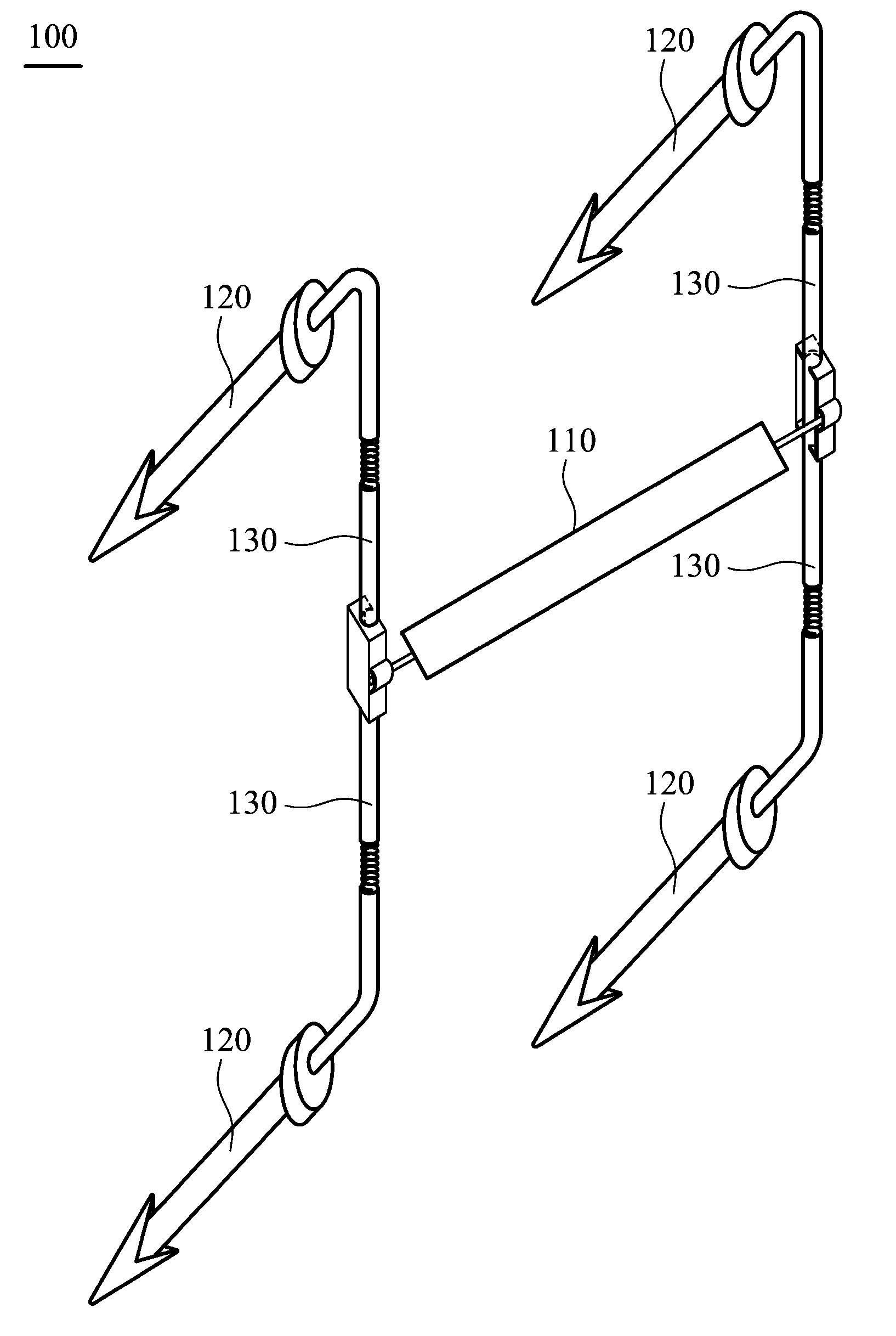
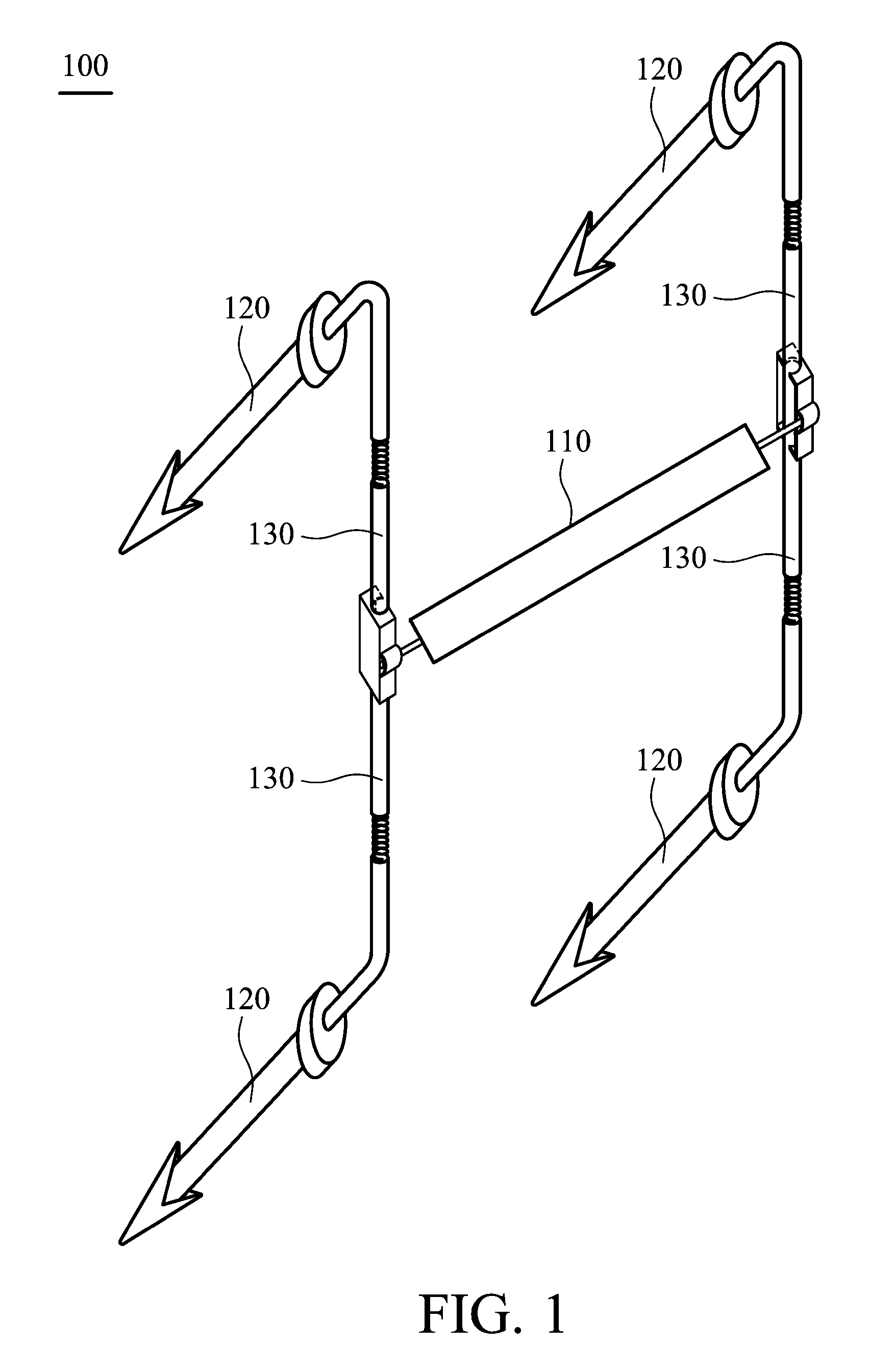
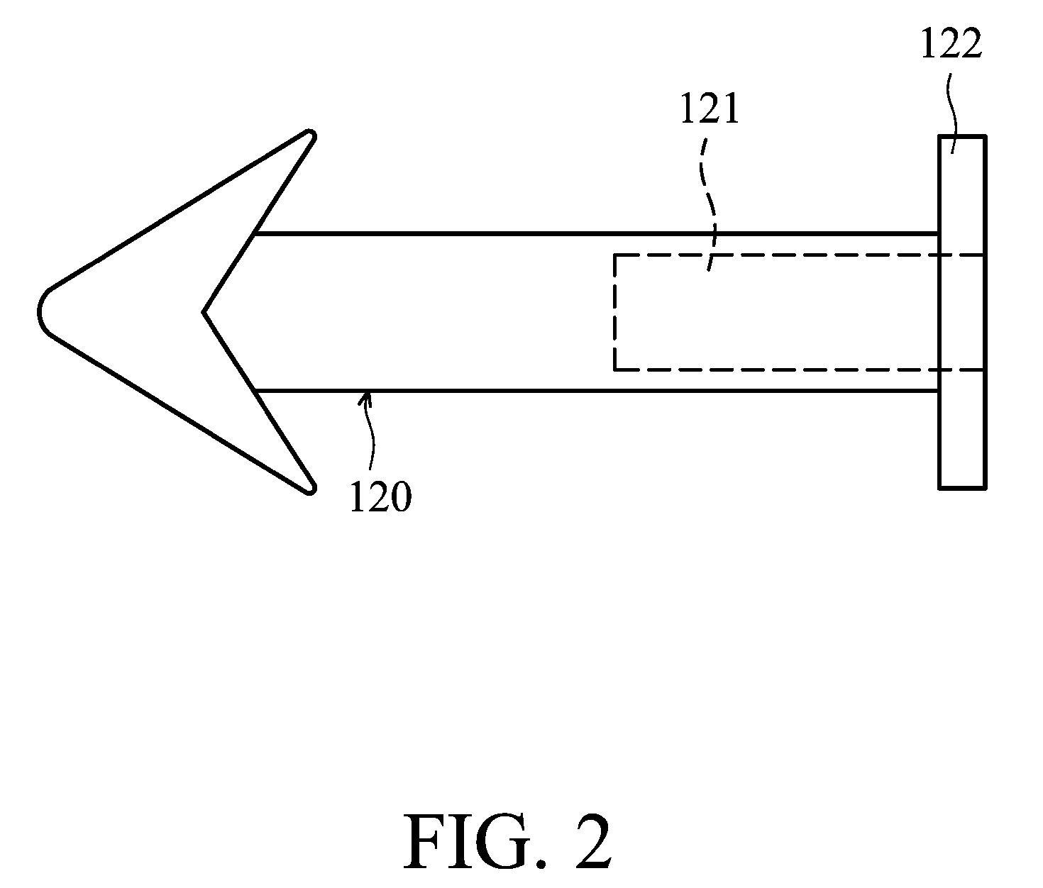
[0062]Referring to FIG. 1, a spinal dynamic stabilization device 100 comprises a supporting member 110, four anchoring members 120 and four connecting members 130.

[0063]The supporting member 110 is made of a bio-compatible material, a porous material, a multi-layered material, a shape memory material or a damping material. If the supporting member 110 is made of an elastic material or is assembled by an elastic mechanism, the structure thereof comprises a concentric circular structure, a mesh structure, a multi-layered structure, a radiate structure, or an artificial disc structure. The structure of the supporting member 110 comprises a hollow pillared structure, porous structure, a sponge structure, a multi-layered structure, a filled structure or an assembled structure. The supporting member 110 is connected to the connecting member 130 by virtue of a clamp 150 for fixing or maintaining dynamic connection. Dynamic connection is defined as the supporting member 110 and the connecti...

second embodiment

[0071]In another embodiment, the elements which are the same as the above-mentioned embodiment are labeled with the same number.

[0072]Referring to FIG. 10, the spinal dynamic stabilization device 100′ comprises a supporting member 110, two anchoring members 120 and two connecting members 130.

[0073]Similarly, each connecting member 130 connects the supporting member 110 to the anchoring member 120, fixing a relative position between the supporting member 110 and the anchoring member 120. The connecting member 130 is connected to the anchoring member 120 via complete fixation or dynamic connection. Dynamic connection is defined as having one end of the supporting member 110 and the connecting member 130 able to move, or two ends of the supporting member 110 and the connecting member 130 able to move.

[0074]Other element structures, characteristics and operating methods of this embodiment that are the same as the above-mentioned embodiment are omitted for brevity.

third embodiment

[0075]Referring to FIG. 12A, the anchoring member 120 is fixed in the vertebra V. At least a groove 127a is installed above the anchoring member 120. The groove 127a is engaged with at least a connecting member 130 or supporting member 110. The anchoring member 120 comprises an inner groove 127b to fix to an inner screw 128a for fixing the connecting member 130. The connecting member 130 is made of a rigid material, an elastic material, or a viscoelastic material, and the connecting member is assembled by a rigid mechanism, an elastic mechanism or a viscoelastic mechanism. The connecting member 130 or the supporting member 110 may be a rope-shaped member, assembled member with a supporting member 132b (the shape may be sleeve-shaped, pillared shaped, plate shaped, or other shaped) (shown in FIG. 12A), a spring 132c or a viscoelastic mechanism (shown in FIG. 12B).

[0076]The connecting member 130 or the supporting member 110 is fixed on the anchoring member 120. The fixing method may b...


PUM


Abstract

A spinal dynamic stabilization device for maintaining an anatomical height between two adjacent vertebras is provided. Each vertebra includes a spinous process and two symmetric pedicles. The spinal dynamic stabilization device includes a supporting member, at least one anchoring member, and at least one connecting member. The supporting member is disposed between the spinous processes. The anchoring member is fixed in one of the vertebra via one of the pedicles. The connecting member connects the supporting member to the anchoring member, fixing a relative position between the supporting member and the anchoring member, further fixing a relative position between the vertebras.

Description

CROSS REFERENCE TO RELATED APPLICATIONS[0001]This Application claims priority of Taiwan Patent Application No. 096140021, filed on Oct. 25, 2007, the entirety of which is incorporated by reference herein.BACKGROUND OF THE INVENTION[0002]1. Field of the Invention[0003]The invention relates to a spinal dynamic stabilization device, and more particularly to a spinal dynamic stabilization device which can correct the normal height between vertebrae of the spine.[0004]2. Description of the Related Art[0005]At present, spondylolisthesis and spinal stenosis are common diseases. Spondylolisthesis usually occurs in workers whom require constant lifting of heavy items and athletes, and is caused by pressure and extra force on the disc. Namely, one of the vertebra of the vertebral column slides forward to a neighboring vertebra. At which time, the vertebra presses central nerves or nerve roots and the patient feels pain. Stenosis is the narrowing of the spinal canal, pathologically caused by a...

Claims


Application Information

Patent Timeline
Patent Type & Authority Applications(United States)
IPC IPC(8): A61B17/70A61B17/04
CPCA61B17/0642A61B17/7001A61B17/7008A61B17/7067A61B17/7041A61B17/7049A61B17/705A61B17/7032
Inventor WENG, YU SHIHYU, CHIA-WEILIN, YI-HUNGWU, I-CHINGYU, YA-JENCHEN, WEN-JERCHUEH, SHAN-CHANGHUANG, CHRIS ING-YIWANG, JAW-LINWANG, SHIAN-YIH
Owner IND TECH RES INST
Why Eureka
Try Eureka