Gas wiping apparatus

a wiping apparatus and gas technology, applied in the direction of coatings, sweetmeats, confectionery, etc., can solve the problems of increasing the overall weight of the gas wiping apparatus, increasing the risk of gas leakage, etc., to prevent the edge from overcoating the steel strip, high pressure, and easy installation

Active Publication Date: 2009-05-07
POHANG IRON & STEEL CO LTD
View PDF5 Cites 14 Cited by
  • Summary
  • Abstract
  • Description
  • Claims
  • Application Information

AI Technical Summary

Benefits of technology

[0030]The gas wiping apparatus in a molten metal coating line of the invention provides various effects as described below.
[0031]First, the upper lip for adjusting a gap of the gas outlet cooperatively with the lower lip is easily installed in a lip support unit while adjusting the gap of the gas outlet stably. That is, the gas outlet is adjustable more precisely.
[0032]Notably, this effectively prevents edge over coating of the steel strip.
[0033]Moreover, a multistage uniform pressure space is defined by the chamber and the lip, and the high pressure gas ejection profile is adjusted in response to a connection between the chamber and the feed pipe, thereby ensuring the high pressure gas to be ejected more uniformly.
[0034]In the end, the gas wiping apparatus of the invention prevents the steel strip from being coated non-uniformly in a width direction and eventually enhances coating quality of the steel strip.

Problems solved by technology

Therefore, to sustain strength of the chamber, the large-sized chamber should be sufficiently thick, thereby increasing an overall weight of the gas wiping apparatus.
This weakens strength of the upper and lower lips and deforms the gas outlet, i.e., gap G between the upper and lower lips, causing the steel strip to be coated non-uniformly in a width direction of the steel strip.
However, in this gas wiping apparatus 300, the upper lip fixed to the lip support unit to adjust the gas outlet is very large-sized.
Thus it is very difficult to install the upper lip in the lip support unit or adjust a gap between the upper and lower lips.
Moreover, the conventional gas wiping apparatus 300 is not designed in response to an ejection profile of a high-pressure gas fed to the chamber through a feed pipe.
Also, the chamber is not provided with a multistage uniform pressure space where the high pressure gas flows.

Method used


Image

  • Gas wiping apparatus
  • Gas wiping apparatus
  • Gas wiping apparatus

Examples


first embodiment

[0058]First, the gas wiping apparatus 1 will be described according to the invention.

[0059]FIGS. 4 and 5 are a structural view and an exploded perspective view illustrating the gas wiping apparatus 1 according to the first embodiment of the invention.

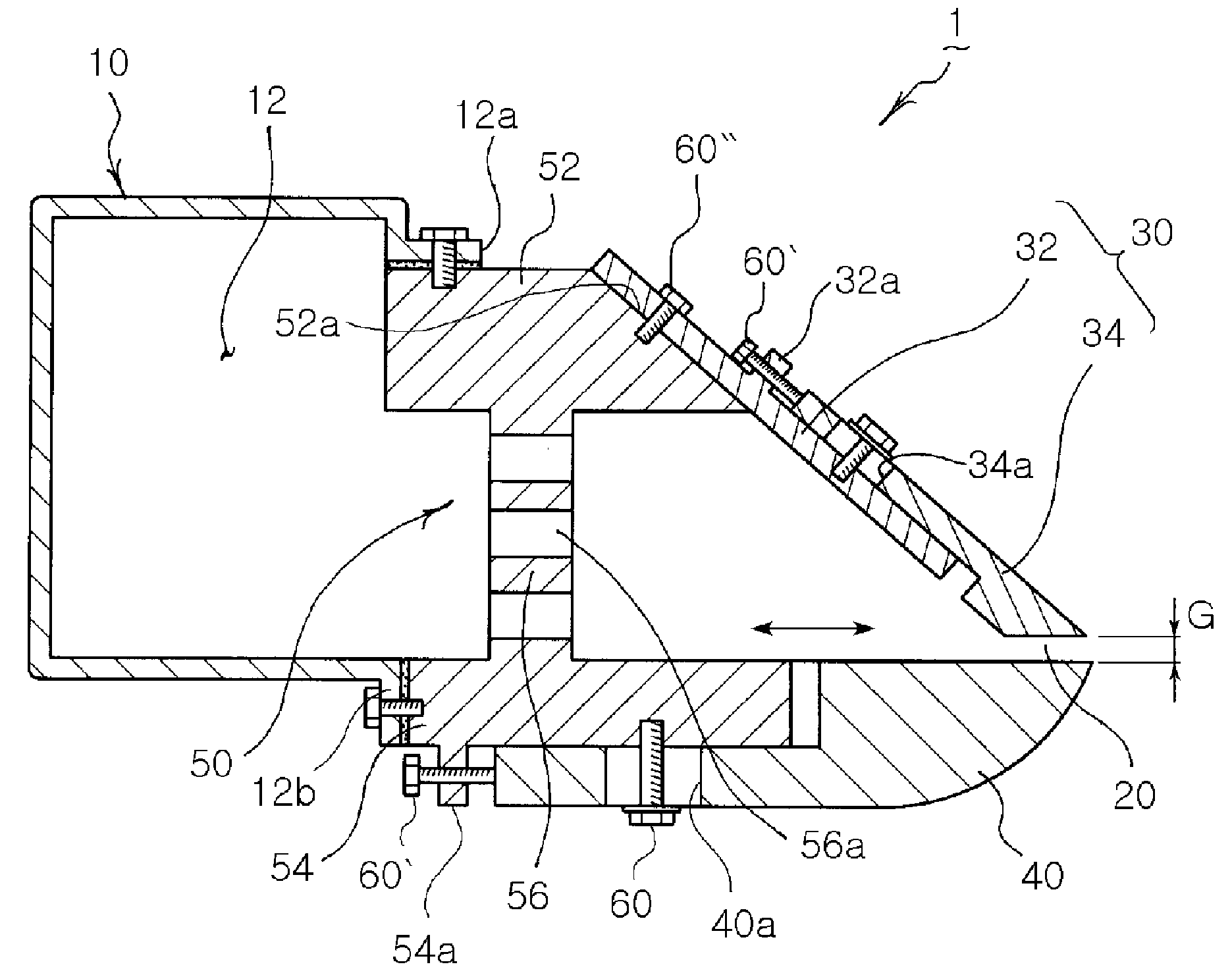
[0060]That is, as shown in FIGS. 4 and 5, the gas wiping apparatus 1 includes a chamber 10, a multiple upper lip 30 and a lower lip 40. The chamber 10 has a space 12 for containing a high pressure gas (air or inactive gas) supplied. The multiple upper lip 30 is joined to the chamber 10. The lower lip 40 is associated with the chamber 10 and defines a gas outlet 20 with a predetermined gap cooperatively with the multiple upper lip 30.

[0061]The gas wiping apparatus 1 of the invention adopts the multiple upper lip 30 in place of the upper lip of the conventional gas wiping apparatus 300 shown in FIG. 3. This allows easier adjustment of the gas outlet 20, i.e., G a gap between the upper and lower lips which practically serves to adjust a co...

second embodiment

[0101]FIGS. 11 to 20 illustrate a gas wiping apparatus 100 according to the invention. However, the same components described in FIGS. 4 to 10 are designated with reference numerals by 10× and will not be described in greater detail.

[0102]First, as shown in FIGS. 11 to 13, the gas wiping apparatus 100 of this embodiment of the invention includes a chamber 110, a lip support unit 150 and upper and lower lips 130 and 140. The chamber 110 has a space 112 for containing a high-pressure gas and defines first and second uniform pressure spaces A1 and A2. The lip support unit 150 is associated in a front of the chamber 110 and defines a third uniform pressure space A3. The lip support unit 150 allows the high pressure gas to flow therethorugh and supports the apparatus against load. The upper and lower lips 130 and 140 are associated with a front of the lip support unit 150 to cooperatively define a gas outlet 120 with a predetermined gap.

[0103]That is, in the gas wiping apparatus 100 of t...


PUM

PropertyMeasurementUnit
lengthaaaaaaaaaa
pressureaaaaaaaaaa
lengthaaaaaaaaaa

Abstract

A gas wiping apparatus for use in coating a molten metal onto a steel strip. In the apparatus, a chamber, to which a high pressure gas is supplied, defines a multistage uniform pressure space. A lip support unit is associated with a front of the chamber to allow the high pressure gas to flow therethrough, the lip support unit supporting the apparatus against load. Upper and lower lips are associated with a front of the lip support unit to cooperatively define an outlet. The upper lip adjusts a gap of a gas outlet cooperatively with the lower lip, and can be easily installed in a lip support unit while adjusting the gap of the gas outlet stably. Also, edge over coating (EOC) of the steel strip can be prevented without an additional auxiliary nozzle.

Description

TECHNICAL FIELD[0001]The present invention relates to a gas wiping apparatus for coating a molten metal such as molten zinc onto a steel strip.[0002]More particularly, the present invention relates to a gas wiping apparatus in a molten coating line in which an upper lip for adjusting a gap of a gas outlet cooperatively with a lower lip can be easily installed in a lip support unit while adjusting the gap of the gas outlet stably, edge over coating (EOC) of the steel strip is prevented, and also a multistage uniform pressure space is defined by a chamber and the lip to allow a high pressure gas to be ejected uniformly in response to a high pressure gas ejection profile, thereby eventually enhancing coating quality of the steel strip.BACKGROUND ART[0003]A coated steel strip obtained by coating a specific molten metal, e.g., molten zinc onto a cold-rolled steel strip or a hot-rolled steel strip, is highly corrosion-resistant and has aesthetic appearance.[0004]For example, the steel str...

Claims


Application Information

Patent Timeline
Patent Type & Authority Applications(United States)
IPC IPC(8): B05C11/06
CPCC23C2/20
Inventor LEE, DONG-EUNCHO, MYUNG-JONGSEON, PAN-WOOKIM, SANG-JOON
Owner POHANG IRON & STEEL CO LTD
Why Eureka
Try Eureka