Spiral flat-tube heat exchanger

a flat-tube heat exchanger and spiral technology, applied in tubular elements, metal-working equipment, lighting and heating equipment, etc., can solve the problems of large height-to-footprint ratio, limited application of flat-plate heat exchangers, and relatively heavy stainless steel typical used in flat-plate heat exchangers, and achieve greater flexibility.

Inactive Publication Date: 2009-05-07
CARRIER CORP
View PDF14 Cites 20 Cited by
  • Summary
  • Abstract
  • Description
  • Claims
  • Application Information

AI Technical Summary

Benefits of technology

[0012]The present invention thus provides an extremely efficient counter flow heat exchanger that provides greater flexibility in terms of physical dimensions as well as control of desired heat transfer properties. These features will allow the present invention to find use in a wide variety of applications. These and other features of the present invention will be appreciated and understood from the following drawings, detailed description, and claims.

Problems solved by technology

This configuration results in a relatively large height-to-footprint ratio.
This height-to-footprint constraint limits the applications for flat plate heat exchangers.
The stainless steel typically used in flat plate heat exchangers is also relatively heavy, and has a relatively high thermal resistance and a low heat transfer coefficient, which also limits its performance.

Method used


Image

  • Spiral flat-tube heat exchanger
  • Spiral flat-tube heat exchanger
  • Spiral flat-tube heat exchanger

Examples


Embodiment Construction

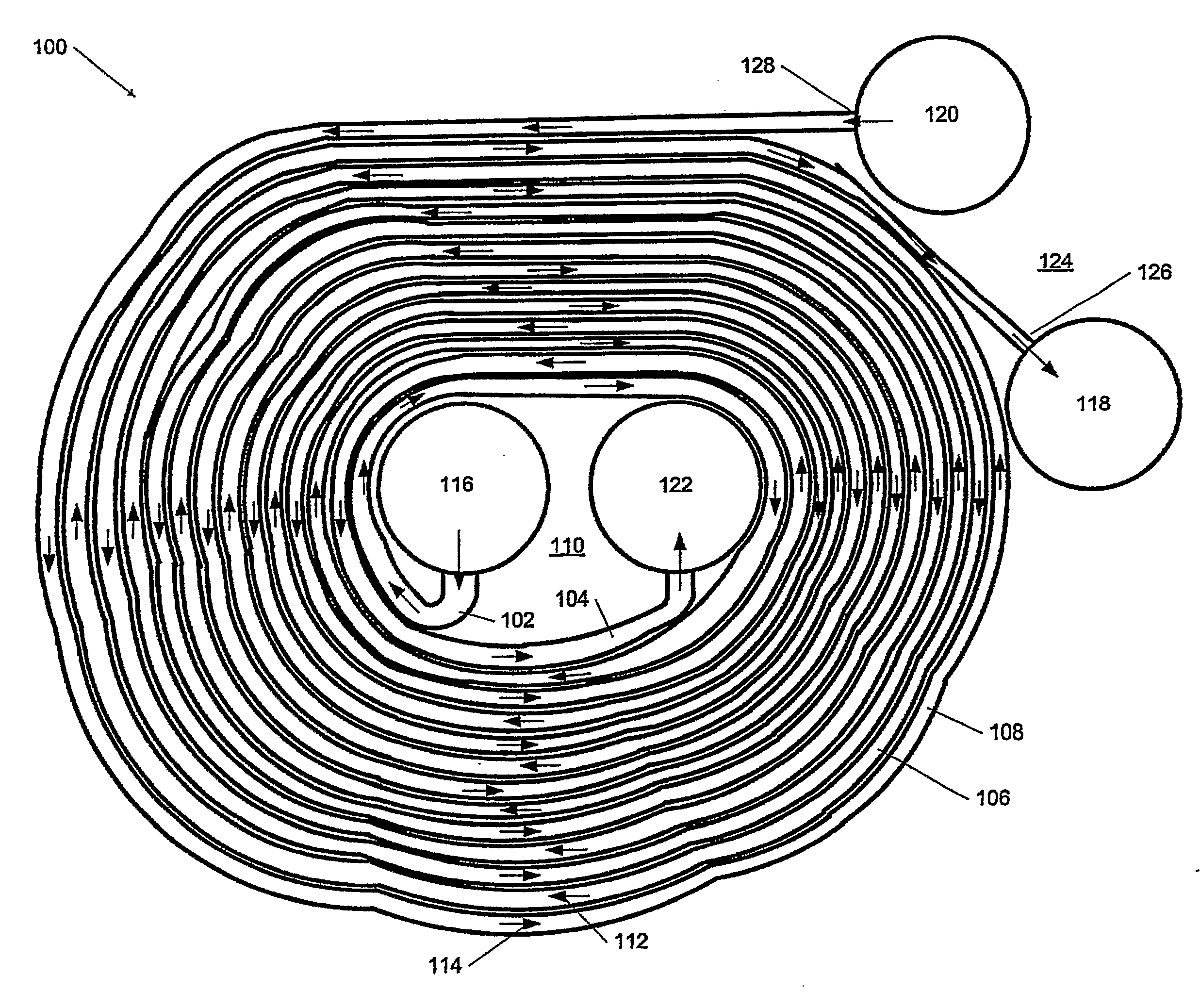
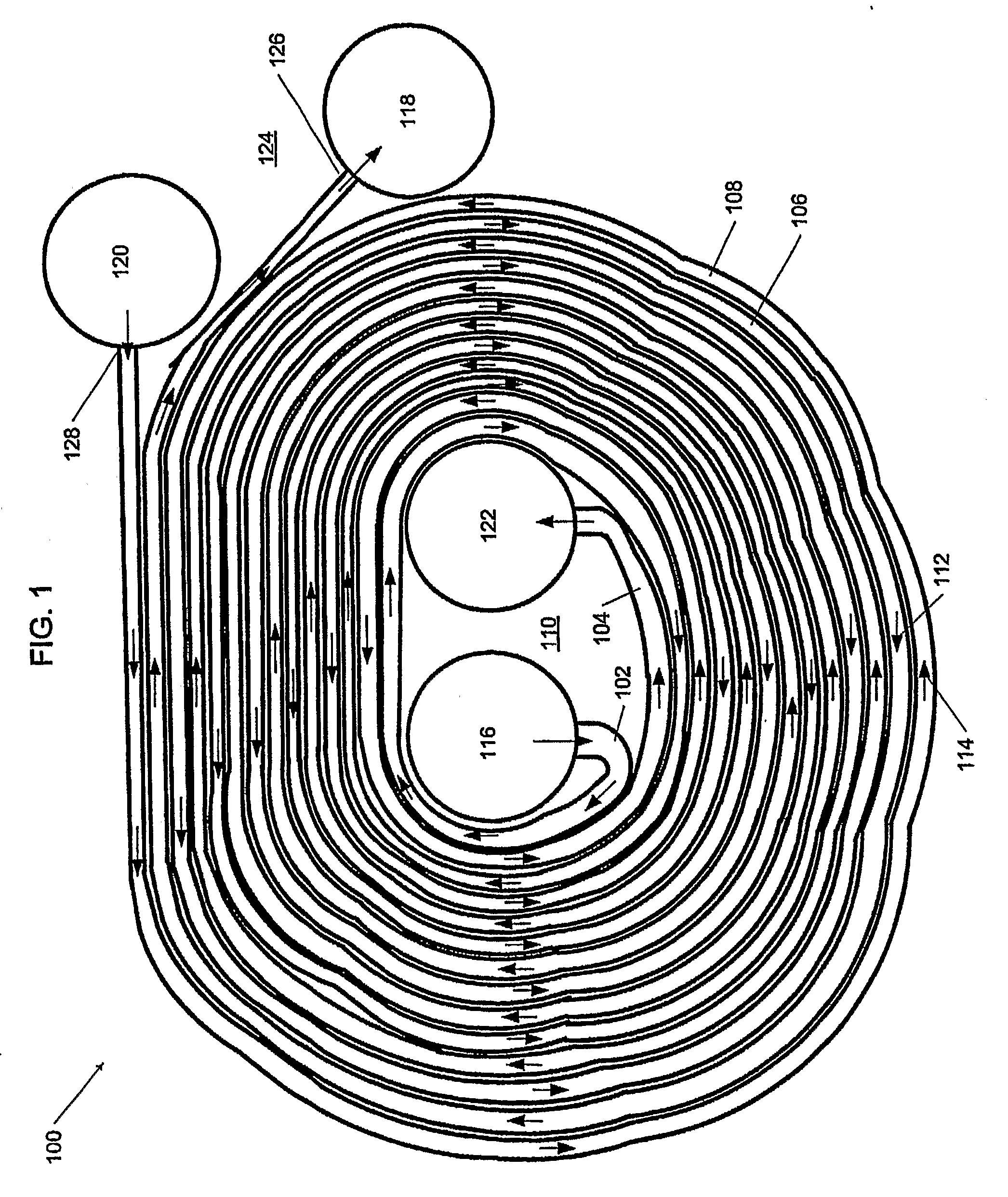
[0019]Referring now to the drawings and in particular to FIG. 1, an exemplary embodiment of a spiral flat-tube heat exchanger is illustrated.

[0020]Heat exchanger 100 includes a first tube 102 and a second tube 104. First tube 102 is thermally coupled to second tube 102, and the tubes are configured to form alternating spirals that are preferably substantially concentric. Substantially concentric means that a first spiral 106 formed by first tube 102 and a second spiral 108 formed by second tube 104 share a common central area 110. As used in this disclosure, the term spiral means an object wound around a fixed central area at a continuously increasing distance from the area. A first working fluid 112 flows through first tube 102 and a second working fluid 114 flows through second tube 104.

[0021]First tube 102 and second tube 104 are in thermal contact, so that heat may be transferred between the first working fluid 112 and the second working fluid 114. In a preferred embodiment, hea...


PUM

PropertyMeasurementUnit
channel widthsaaaaaaaaaa
areaaaaaaaaaaa

Abstract

A spiral flat tube heat exchanger comprising a first flat tube and a second flat tube thermally coupled to the first flat tube, the first flat tube and the second flat tube forming substantially concentric spirals. A first fluid flows through the first flat tube in a first flow direction, and second fluid flows through the second flat tube in a second flow direction. The flat tubes preferably contain microchannels to increase heat transfer efficiency.

Description

BACKGROUND OF THE INVENTION[0001]1. Field of the Invention[0002]The present invention generally relates to heat exchangers. More particularly, the present invention relates to a counterflow heat exchanger having flat tubes configured to form concentric spirals. The flat tubes may include interior microchannels.[0003]2. Description of the Related Art[0004]Counterflow heat exchangers for gases and liquids are known, and typically include an inlet and an outlet for each of two or more fluids. The fluids generally do not mix and follow separate flow paths within the heat exchanger. The most common types of counterflow heat exchangers include flat plate, tube in tube and shell and tube heat exchangers. Shell and tube heat exchangers generally have a series of small tubes within a larger pressure vessel or shell. Heat is transferred between a fluid flowing within the small tubes and another fluid flowing within the shell.[0005]In a flat plate heat exchanger, heat is transferred between tw...

Claims


Application Information

Patent Timeline
Patent Type & Authority Applications(United States)
IPC IPC(8): F28F1/00B21D53/02
CPCF28D7/0033F28D7/04F28D2021/007Y10T29/4935F28F2260/02F28F2275/025F28F2013/006F28D2021/0071
Inventor GRABON, MICHEL
Owner CARRIER CORP
Why Eureka
Try Eureka