High-deformation composite microresonator

Inactive Publication Date: 2009-05-07
COMMISSARIAT A LENERGIE ATOMIQUE ET AUX ENERGIES ALTERNATIVES
View PDF6 Cites 10 Cited by
  • Summary
  • Abstract
  • Description
  • Claims
  • Application Information

AI Technical Summary

Problems solved by technology

Two systems derived from conventional components are used to obtain electrical resonance:RLC circuits that can easily be integrated onto wafers but have poor performances,quartz resonators that have high performances but cannot be integrated into a manufacturing process based on the micro-system technology.
This results in a high cost and large size.
However, they are large (1 cm2), cannot be integrated in mi

Method used


Image

  • High-deformation composite microresonator
  • High-deformation composite microresonator
  • High-deformation composite microresonator

Examples


Example

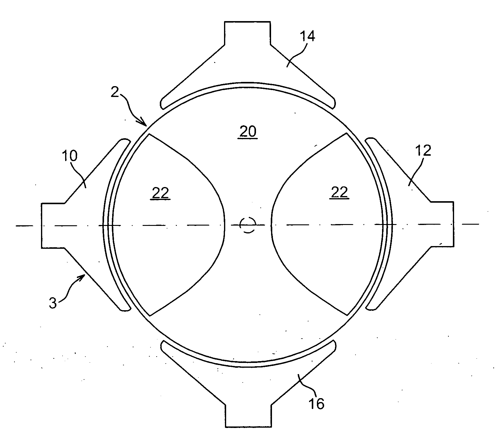
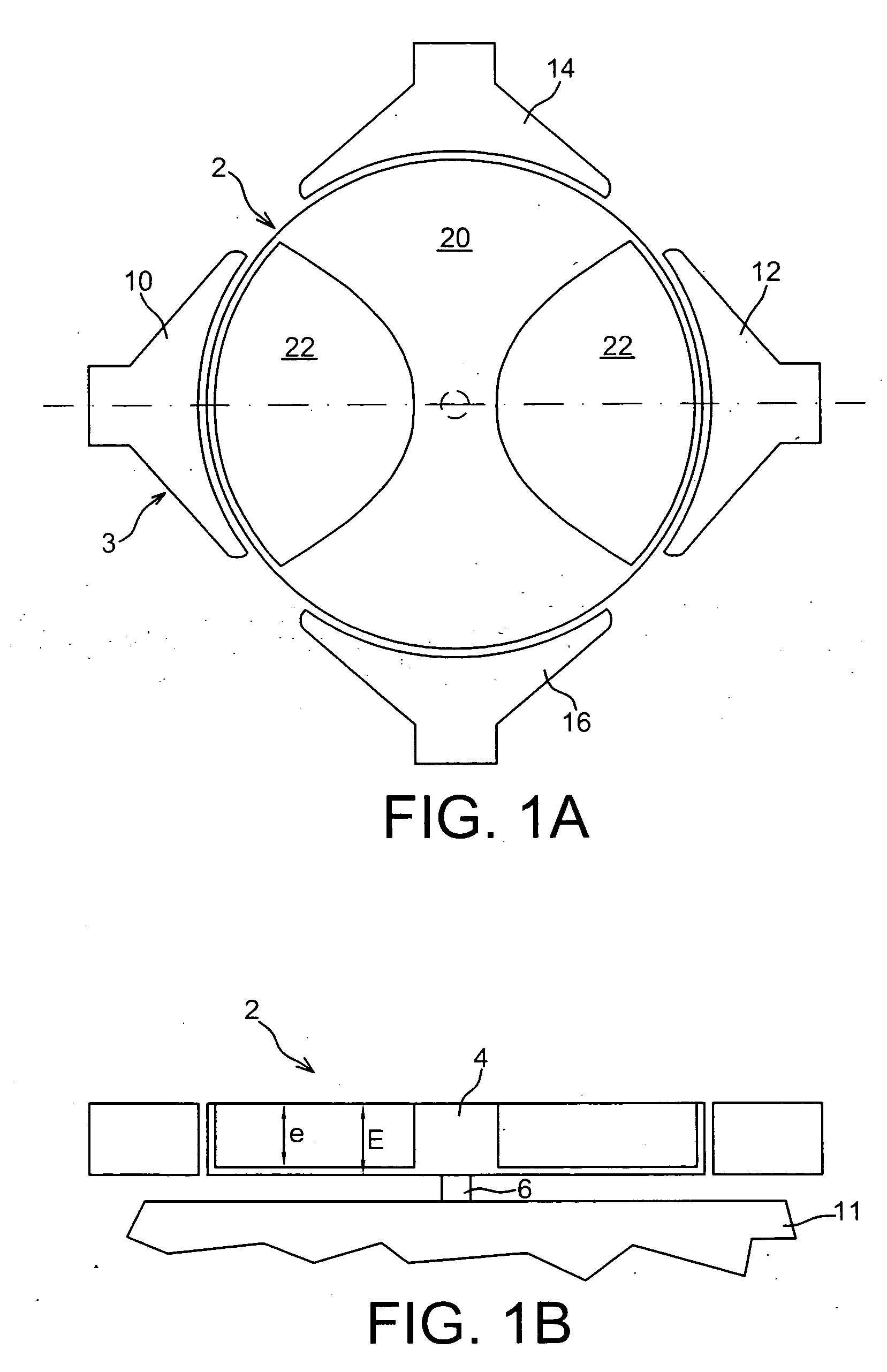
[0052]A first embodiment of the invention will now be described with reference to FIGS. 1A and 1B.

[0053]This is an example of a cylindrical type resonator with capacitive transduction. But it may also relate to plate type resonators and more generally to volume wave resonators.

[0054]The proposed component consists of two distinct parts 2, 3.

[0055]A first part 2 is dedicated to mechanical resonance. It comprises a vibrating body and means 6 anchoring the body to a substrate 11. It is a “composite” cylinder (composed of at least two distinct materials), anchored at the centre of one of its bases by a cylindrical base 6 of small dimensions.

[0056]A second transduction part 3 is aimed at creating a mechanical signal from an electrical signal (excitation) and vice versa. Detection is separate in the case of a component with two ports but in all cases, detection is not necessarily separate from excitation.

[0057]In this second part, there are one or several detection electrodes 10, 12 and a...


PUM

PropertyMeasurementUnit
Fractionaaaaaaaaaa
Fractionaaaaaaaaaa
Fractionaaaaaaaaaa

Abstract

An electromechanical resonator including a vibrating body, at least one excitation electrode, and at least one detection electrode. The vibrating body includes a first part made of a first material with a first Young's modulus and a second part made of a second material with a second Young's modulus, less than the first Young's modulus, the second part being at least partially located facing the detection electrode.

Description

TECHNICAL DOMAIN AND PRIOR ART[0001]This invention relates to the domain of microresonators.[0002]Microresonators are used for example in the field of mobile telephony in the composition of filters, VCOs (voltage control oscillators) and reference oscillators.[0003]Resonator type components preferably with the following characteristics are required in order to achieve integration:[0004]small dimensions,[0005]variable resonant frequencies (from less than a few MHz to more than a few GHz),[0006]high quality factor,[0007]low signal losses (highest possible output level), which requires strong electromechanical coupling,[0008]very good stability in temperature and in time,[0009]compatibility with microelectronic processes.[0010]Two systems derived from conventional components are used to obtain electrical resonance:[0011]RLC circuits that can easily be integrated onto wafers but have poor performances,[0012]quartz resonators that have high performances but cannot be integrated into a ma...

Claims


Application Information

Patent Timeline
IPC IPC(8): H02N11/00H01L41/22B81B3/00H01L41/332H03H3/007H03H9/46
CPCB81B3/0078B81B2201/0271B81B2203/0118Y10T29/42H03H9/2436H03H2009/02503H03H3/0072
Inventor TRIPARD, AMYOTBRECHET, YVES
Owner COMMISSARIAT A LENERGIE ATOMIQUE ET AUX ENERGIES ALTERNATIVES
Why Eureka
Try Eureka