Status indicator

a status indicator and status technology, applied in the field of status indicators, can solve the problems of complex monitoring of the operation of these devices, small devices, and and achieve the effect of reducing the hysteresis of the status indicator

Active Publication Date: 2009-05-07
VERIS INDS
View PDF10 Cites 54 Cited by
  • Summary
  • Abstract
  • Description
  • Claims
  • Application Information

AI Technical Summary

Problems solved by technology

Many industrial, commercial and residential environments incorporate large numbers of electrical loads that are widely distributed geographically and often located in sites where access is difficult.
Many these devices are small and draw very limited amounts of current, commonly less than 20 amps and, often, only a fraction of an amp.
Monitoring the operation of these devices is complicated by their remoteness from the monitoring location and the remoteness of the controller for the device which is often equally remote from the device and the monitoring location.
The hysteresis of the precision voltage detector is typically less than five percent of the device's detection voltage but the hysteresis of the status indicator can be substantially greater because the operation of other portions of the current sensor exacerbate the hysteresis of the precision voltage detector.

Method used


Image

  • Status indicator
  • Status indicator
  • Status indicator

Examples


Embodiment Construction

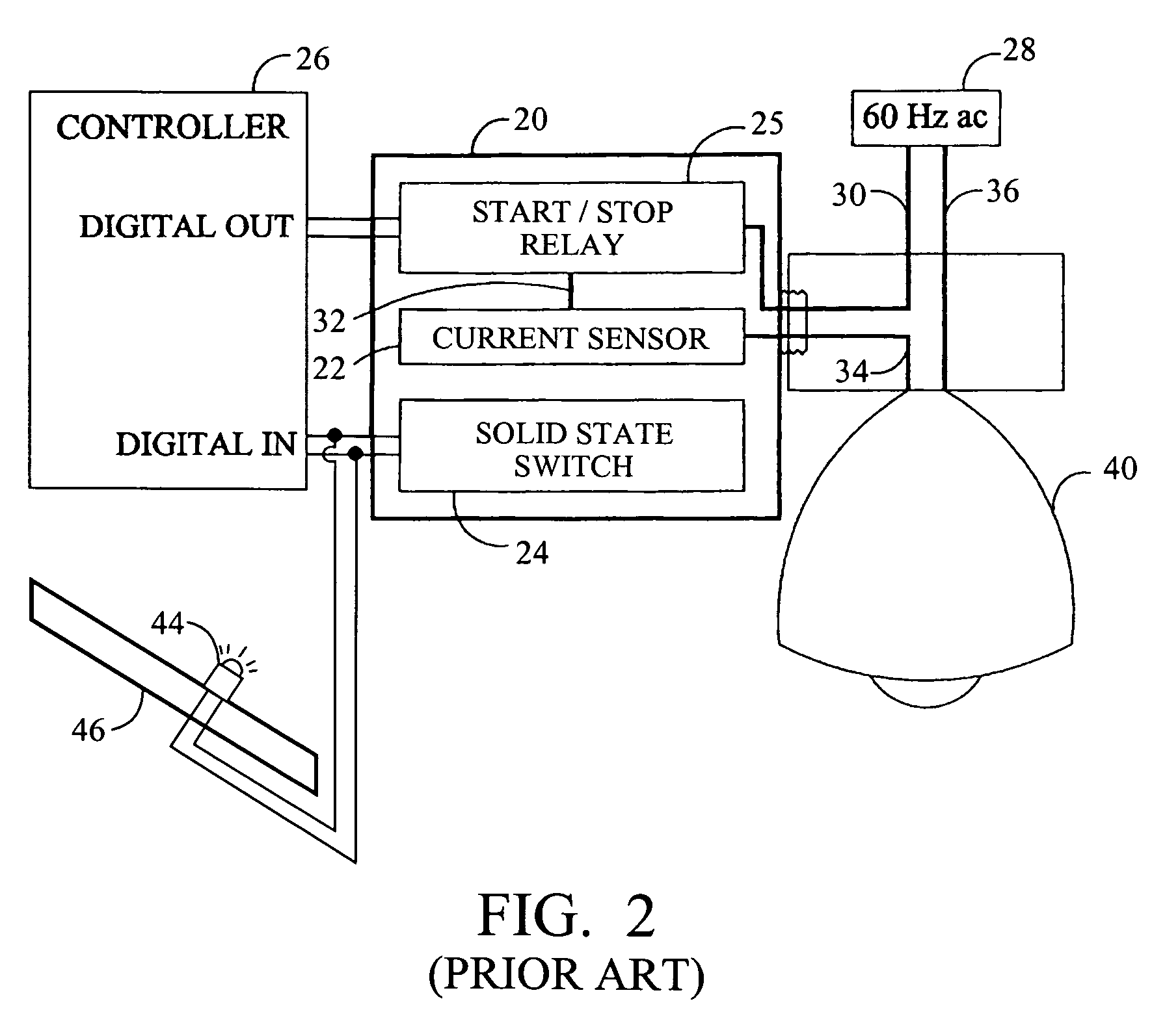
[0013]Referring in detail to the drawings where similar parts are identified by like reference numerals, and, more particularly to FIG. 2, the operation of a remotely located electrical circuit is commonly monitored by a status indicator 20 that includes a current sensor 22 and a solid state switch 24 often in combination with a relay 25. The start / stop relay 25 is energized or otherwise controlled by a digital output of a controller 26 and is interconnected with a power source 28 by a wire 30. A conductive loop for current flow back to the power source includes the wire 32 interconnecting the relay and the current sensor, the wire 34 interconnecting the current sensor and the load 40, a light in the exemplary circuit, and the wire 36 interconnecting the load and the power source. When the start / stop relay is open, as a result of a control signal from the controller, the power to the load is interrupted (open circuit). Likewise, when the start / stop relay is closed, as a result of a ...


PUM


Abstract

The sensitivity and accuracy of a status indicator for sensing a current in an electrical circuit is improved by shifting the reference level of the transformer output to maximize the input signal to a precision voltage detector and by reducing the hysteresis of the status indicator by balancing the burden of the current transformer during the positive and negative alternations of the AC signal and by driving secondary loads with a voltage to current converter.

Description

CROSS-REFERENCE TO RELATED APPLICATIONS[0001]This application claims the benefit of U.S. Provisional App. No. 60 / 993,213, filed Sep. 10, 2007.BACKGROUND OF THE INVENTION[0002]The present invention relates to a device for monitoring electric current in a cable connecting a load and a power source.[0003]Many industrial, commercial and residential environments incorporate large numbers of electrical loads that are widely distributed geographically and often located in sites where access is difficult. Many these devices are small and draw very limited amounts of current, commonly less than 20 amps and, often, only a fraction of an amp. However, the operation of these loads, for example, fan motors or lights can be important to maintaining a safe environment or the successful completion of a process that may involve costly or hazardous equipment or materials. Monitoring the operation of these devices is complicated by their remoteness from the monitoring location and the remoteness of th...

Claims


Application Information

Patent Timeline
Patent Type & Authority Applications(United States)
IPC IPC(8): G01R19/22G08B21/00G01R15/18
CPCG01R15/183
Inventor HUNTER, PHILLIP
Owner VERIS INDS
Why Eureka
Try Eureka