Droplet ejection device for a highly viscous liquid

Active Publication Date: 2009-05-07
IND TECH RES INST
View PDF6 Cites 25 Cited by
  • Summary
  • Abstract
  • Description
  • Claims
  • Application Information

AI Technical Summary

Benefits of technology

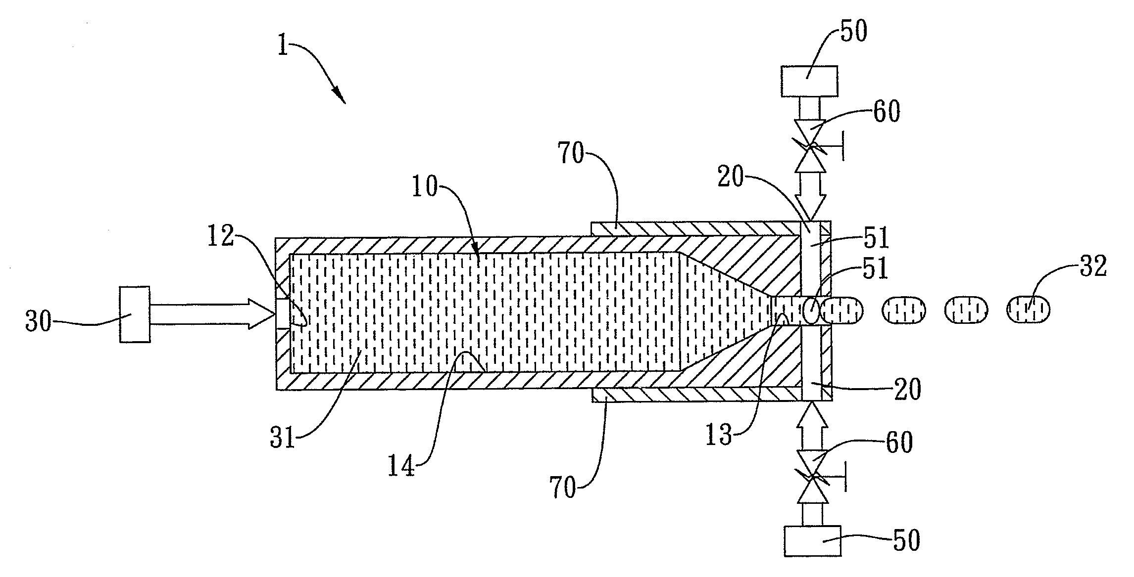
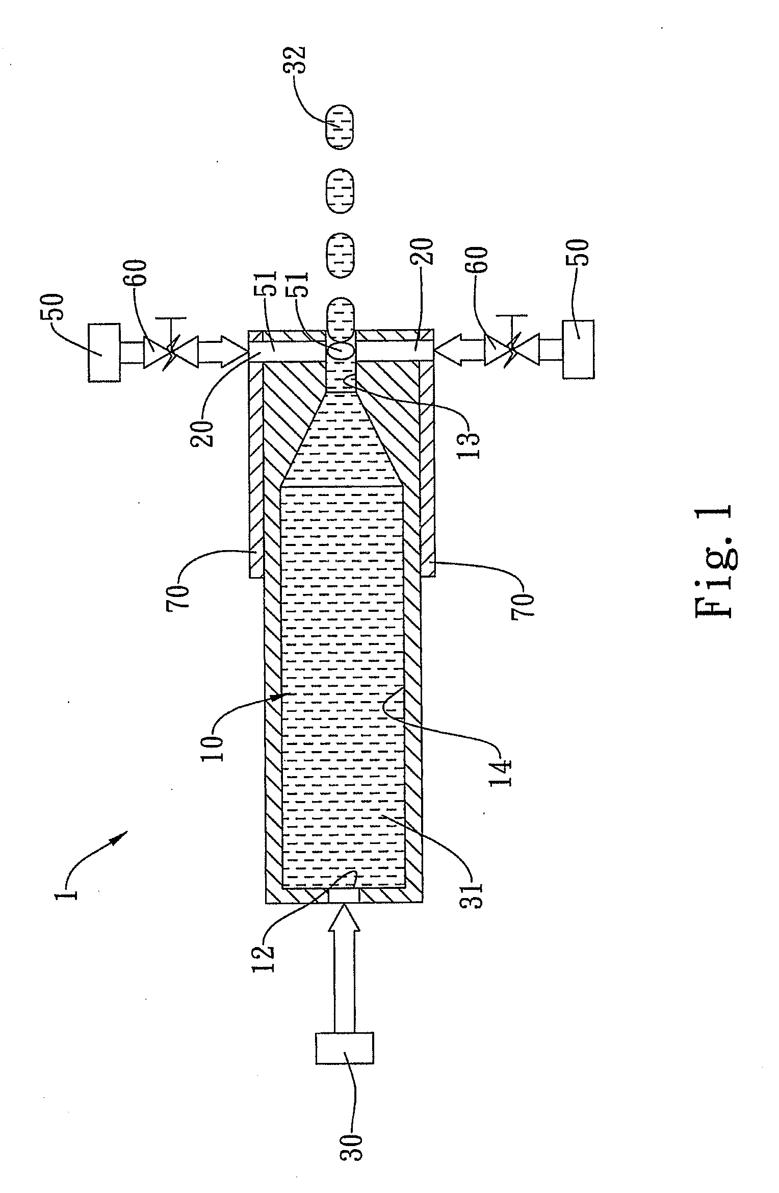
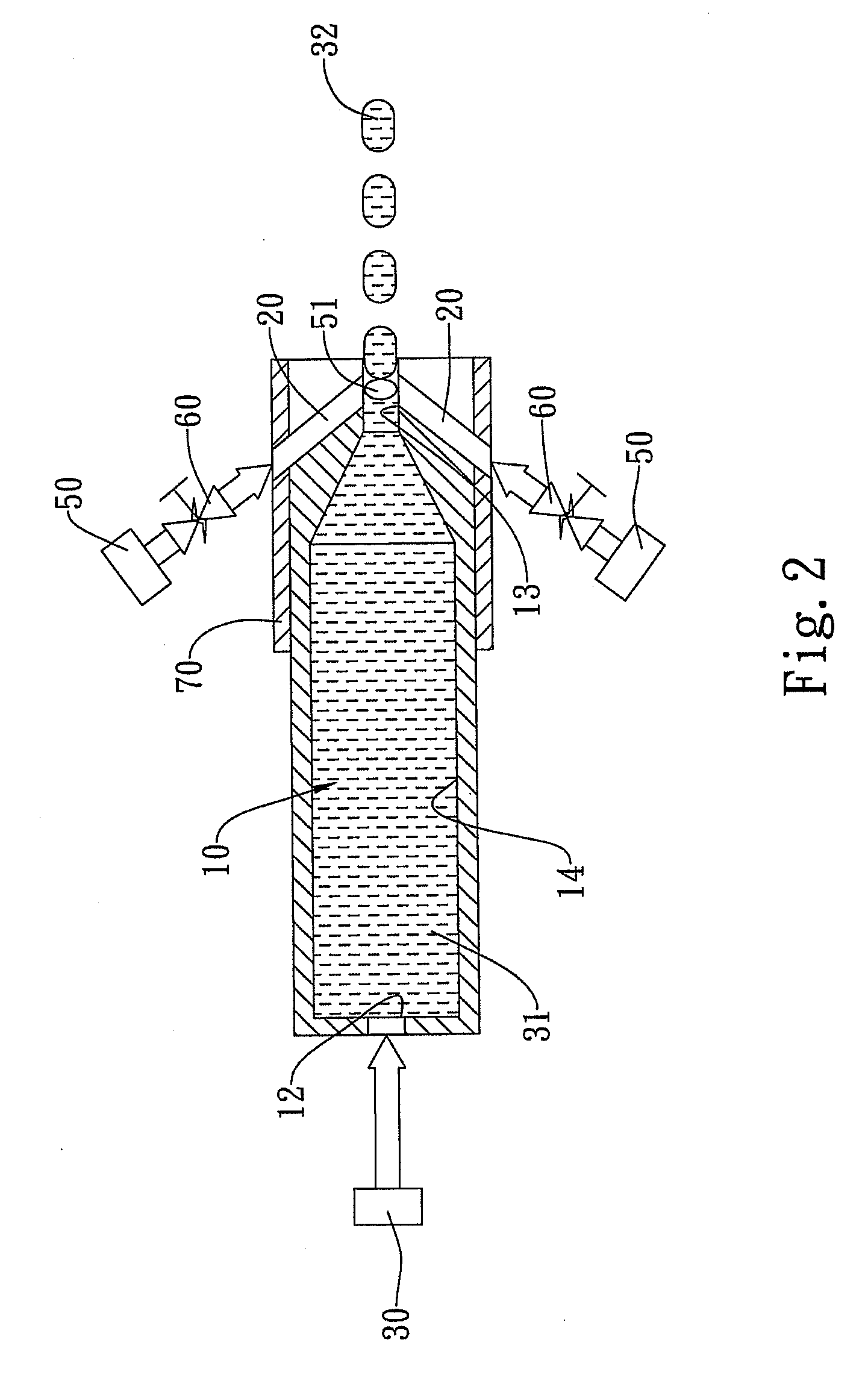
[0020]Accordingly, the present invention is able to control the size of the droplet while ejecting highly viscous liquid. Moreover, as shown in FIG. 10, the present invention has succeeded in atomizing the ejected highly viscous liquid in favor of digital ejection, further paving the way for the application of the invention in direct ejection for microcircuit printing technology.

Problems solved by technology

However, the application of this technology is constrained by the viscosity requirement as low as a few tens cP.
Given its extremely high viscosity, such kind of liquid can only be ejected in large quantities by the machinery equipment or applied to the surface of the target subject in large areas, unable to be atomized for digital ejection.

Method used


Image

  • Droplet ejection device for a highly viscous liquid
  • Droplet ejection device for a highly viscous liquid
  • Droplet ejection device for a highly viscous liquid

Examples


first embodiment

[0036]FIG. 7 shows a schematic view of the fluid transmission line in the droplet ejection module for a highly viscous liquid according to the present invention. This embodiment comprises a first fluid transmission line 2300 communicated with a plurality of third openings 2500 disposed between the first fluid transmission line 2300 and the first openings 2100, allowing the highly viscous liquid 4100 to enter the micro flow channels 1200 by way of the first fluid transmission line 2300. More specifically, in this embodiment, the highly-viscous-liquid supply device 4000 provides the highly viscous liquid 4100 to the first fluid transmission line 2300 before the highly viscous liquid 4100 enters individual branch fluid transmission lines 2310 and exits the third openings 2500. This embodiment also comprises a plurality of second fluid transmission lines 2420 communicated respectively with a plurality of fourth openings 2600 disposed between the second fluid transmission lines 2420 and ...

second embodiment

[0037]FIG. 8 shows a schematic view of the fluid transmission line in the droplet ejection module for a highly viscous liquid according to the present invention. This embodiment comprises a plurality of first fluid transmission lines 2310 communicated respectively with a plurality of third openings 2500 disposed between the first fluid transmission lines 2310 and the first openings 2100, allowing a plurality of highly-viscous-liquid supply devices 4000 to provide the highly viscous liquid 4100 to the plurality of first fluid transmission lines 2310, respectively, before the highly viscous liquid 4100 enters individual micro flow channels 1200. This embodiment also comprises a plurality of second fluid transmission lines 2410 communicated respectively with a plurality of fourth openings 2600 disposed between the second fluid transmission lines 2410 and the second openings 2200, allowing a plurality of gas supply devices 5000 to provide the air 5100 to the plurality of second fluid tr...


PUM


Abstract

A droplet ejection device for a highly viscous liquid includes a micro flow channel filled with a highly viscous liquid and having an inlet and an outlet channel; at least a branch channel communicated with the outlet channel; a highly-viscous-liquid supply device connected to the inlet so as to supply the highly viscous liquid to the micro flow channel; a gas supply device connected to the branch channel so as to supply a gas to the outlet channel by way of the branch channel; and at least a control valve mounted between the branch channel and the gas supply device so as to control an intermittent supply of the gas from the branch channel to the outlet channel to interrupt the highly-viscous-liquid flow in the outlet channel and to prompt the highly viscous fluid to form a droplet to be ejected out of the micro flow channel.

Description

BACKGROUND OF THE INVENTION[0001]1. Field of the Invention[0002]The present invention provides a droplet ejection device for a highly viscous liquid, particularly an ejection device capable of intermittent discharge of highly viscous liquid droplets.[0003]2. Description of the Related Art[0004]Digital ejection technology usually atomizes liquid for ejection purposes. However, the application of this technology is constrained by the viscosity requirement as low as a few tens cP. Digital ejection technology was first applied to packing machines in the early years, serving to further identify the features and conditions of the product by ejecting droplets to the target subject to form appropriate images and characters. Such packing machines are available through Japanese companies such as Marsh (U.S. Pat. No. 4,378,564) and Hitachi (U.S. Pat. No. 4,849,909). However, as mentioned earlier, digital ejection technology works only with liquid whose viscosity is no more than a few tens cP, ...

Claims


Application Information

Patent Timeline
IPC IPC(8): B41J2/19
CPCB41J2202/02B41J2/04
Inventor PENG, YU-YINCHIEN, CHIN-PINGAU, TIEN-HO
Owner IND TECH RES INST
Why Eureka
Try Eureka