Image Scanning Device and Image Scanning Method

a scanning device and image technology, applied in the field of image scanning devices, can solve the problems of not being able to reduce the memory capacity needed to store scanned data, the operation of the image sensor cannot be set, and the document cannot be detected in actual size, so as to reduce the amount of memory, without the risk of increasing processing time,

Inactive Publication Date: 2009-05-07
SEIKO EPSON CORP
View PDF9 Cites 9 Cited by
  • Summary
  • Abstract
  • Description
  • Claims
  • Application Information

AI Technical Summary

Benefits of technology

[0010]An object of the present invention is to provide technology for implementation in a pass-through image scanning device, whereby in the event that a mixed load of documents of differing size is loaded into the automatic document feeder, scanning of the documents can be carried out appropriately for each document size without risk of increased processing time. Another object is to reduce the amount of memory needed to store the scanned data. Still another object is to produce output image data from which unneeded image data has been eliminated.
[0011]According to an aspect of the present invention, there is provided an image scanning device. The image scanning device includes an automatic document feeder, an image reader, a memory, a scanning operation controller, and an image processor. The scanning operation controller allocates a scanned image memory area of a predetermined document size within the memory, and stores the image data of the scanned document to the scanned image memory area. The image processor eliminates unneeded data from the data in the scanned image memory area of the predetermined document size to thereby produce output image data, based on a document size of the scanned document that is detected after the automatic document feeder has initiated the feed of the document to the image reader.
[0012]According to the image scanning device, the scanned image memory area will be allocated on the assumption that the size of the document is equal to a prescribed document, and the image data of the scanned document is stored to the scanned image memory area, whereby it will be possible to reduce the memory capacity needed to store the scanned data. Furthermore, output image data can be created by eliminating unneeded data from the data stored in the scanned image memory area, on the basis of the scanned document size detected subsequent to the feed of the document. Accordingly when a mixed load of documents of differing size is loaded into to the automatic document feeder, scanning of the documents can be carried out appropriately for each document size without risk of increased processing time; the amount of memory needed to store the scanned data can be reduced; and output image data from which unneeded data has been eliminated can be created.

Problems solved by technology

However, if documents of different sizes are placed on the document loading stage, the document size detecting means provided to the document loading stage will only be able to detect the largest size of the document in the lengthwise direction (direction parallel to the feed direction) and the largest size of the document in the width direction (direction perpendicular to the feed direction) from among the multiple documents of varying size.
As a result, it is not possible to detect the actual size of the document prior to scanning the document, nor could necessary sections of a document be distinguished from unneeded sections, and thus the operation of the image sensor cannot be set so as to scan only an image of the required area of the documents fed to it.
However, a problem with the device taught in JP2003-101769A is that since preliminary page data is created on the assumption of an original of prescribed size equivalent to the largest document size that the pass-through scanner is capable of copying, no reduction in the memory capacity needed to store the scanned data will be possible.
Another problem is that since prior to scanning the document actual document width cannot be detected and necessary portions of the document cannot be distinguished from unneeded portions, operation of the image sensor cannot be set so as to scan only an image of a desired area of the document fed to it.

Method used


Image

  • Image Scanning Device and Image Scanning Method
  • Image Scanning Device and Image Scanning Method
  • Image Scanning Device and Image Scanning Method

Examples


Embodiment Construction

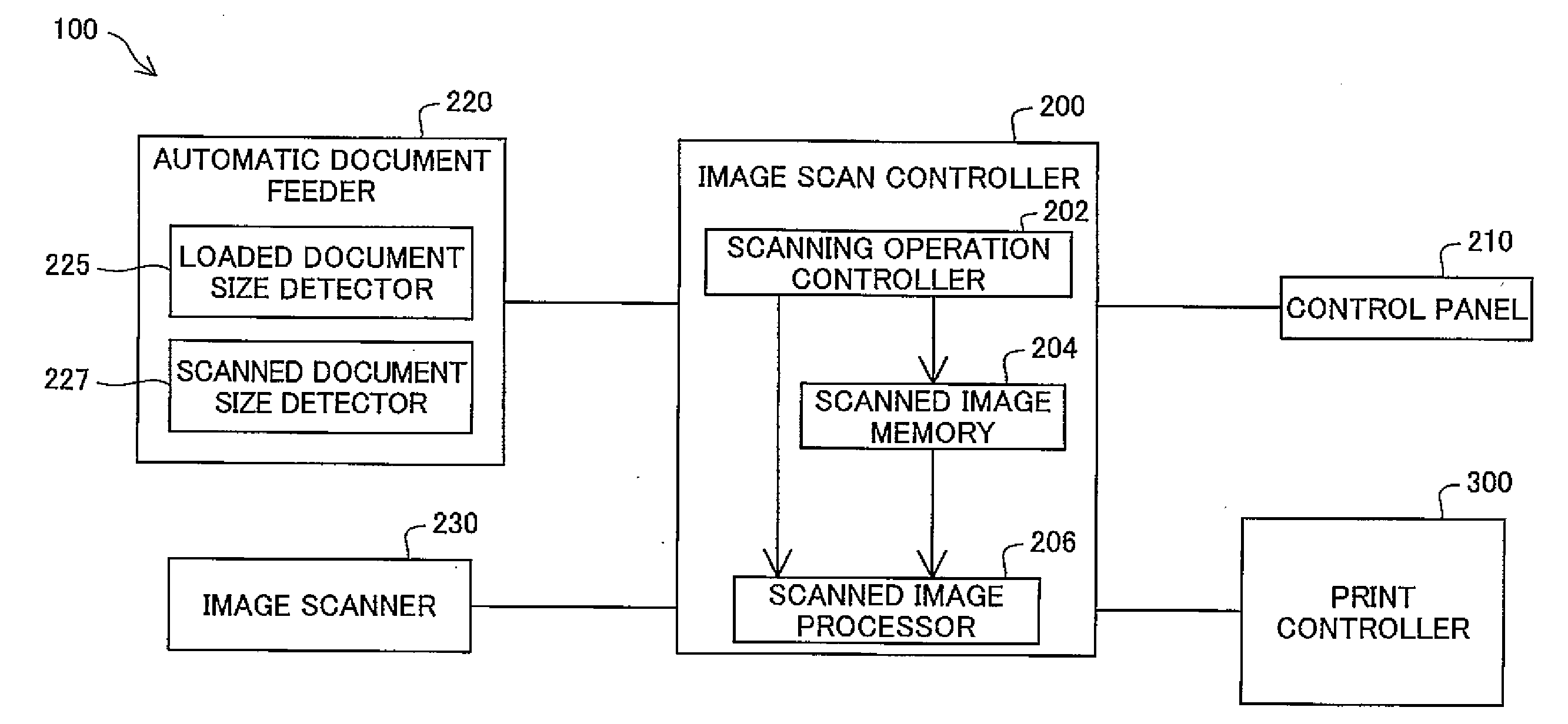
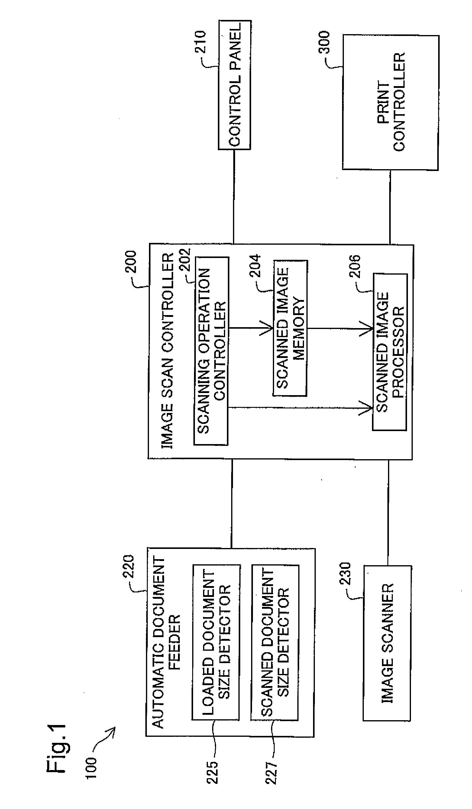
[0018]FIG. 1 is a block diagram depicting the principal parts of a copier device in which an image scanning device according to an embodiment of the present invention is implemented. This copier device 100 includes an image scan controller 200 that controls operation of the image scanning device that scans documents; and a print controller 300 that controls operation of a printing unit that outputs images represented by image data of scanned documents. A control panel 210, an automatic document feeder (ADF) 220, and an image scanner 230 are connected to the image scan controller 200. The image scanner 230 may be also referred to as “image reader 230.”

[0019]The image scan controller 200 and the print controller 300 are each equipped with a CPU, memory, and so on (not shown). Their respective functions are carried out through execution by the CPU of various programs stored in memory.

[0020]The image scan controller 200 has a scanning operation controller 202, a scanned image memory 204...


PUM


Abstract

The scanning operation controller allocates a scanned image memory area of a predetermined document size within a memory, and stores the image data of the scanned document to the scanned image memory area. The image processor eliminates unneeded data from the data in the scanned image memory area of the predetermined document size to thereby produce output image data, based on a document size of the scanned document that is detected after the automatic document feeder has initiated the feed of the document to the image reader.

Description

CROSS-REFERENCE TO RELATED APPLICATIONS[0001]The present application claims the priority based on Japanese Patent Application No. 2007-289219 filed on Nov. 7, 2007, the disclosure of which is hereby incorporated by reference in its entirety.BACKGROUND OF THE INVENTION[0002]1. Field of the Invention[0003]The present invention relates to an image scanning device of pass-through type.[0004]2. Description of the Related Art[0005]A pass-through scanner has a fixed image sensor and an automatic document feeder (ADF) that feeds to the image sensor a document which has been placed on the document loading stage of the ADF. The image sensor sequentially scans the document as it is fed in.[0006]If documents that have been placed on the document loading stage are all of the same size, on the basis of document size which has been detected previously by document size detecting means provided to the document loading stage, the image sensor will be set so as to scan only an image of the required ar...

Claims


Application Information

Patent Timeline
Patent Type & Authority Applications(United States)
IPC IPC(8): G06K9/48H04N1/04
CPCH04N1/00588H04N1/00591H04N1/00602H04N1/0062H04N1/00631H04N1/38H04N1/0071H04N1/00713H04N1/00745H04N1/00748H04N1/00681
Inventor KASAI, EIJI
Owner SEIKO EPSON CORP
Why Eureka
Try Eureka