Advanced technology frame structure with backward compatibility

a technology frame structure and advanced technology, applied in the field of advanced technology frame structure, can solve the problems of bottlenecking system improvement, communication system risk becoming obsolete, and two independent systems being costly approaches to providing legacy suppor

Inactive Publication Date: 2009-05-07
MONUMENT BANK OF INTPROP LLC
View PDF18 Cites 92 Cited by
  • Summary
  • Abstract
  • Description
  • Claims
  • Application Information

AI Technical Summary

Benefits of technology

[0008]An advanced technology frame structure with backward compatibility and associated methods and systems are described herein. As a specific example, the frame structure, methods and systems herein described can be applied in a WiMax Orthogonal Frequency Division Multiple Access (OFDMA) communication system, although their use is not limited thereto. The advanced technology frame structure supports legacy devices with little or no change to and minimal effect on the legacy devices and enables the use of new physical layer and MAC layer enhancements that are not supported by the legacy system. In one demonstrative embodiment, the advanced technology frame structure can enhance the existing frame structure in dimensions of time, frequency, or a combination of time and frequency. In another demonstrative embodiment, the advanced technology frame structure time division multiplexes advanced technology subframes with the existing downlink and uplink subframes. For example, the existing downlink subframe can be divided into a legacy downlink subframe and an advanced technology downlink subframe. Similarly, the existing uplink subframe can be divided into a legacy uplink subframe and an advanced technology uplink subframe.

Problems solved by technology

It is a constant challenge for communication systems to integrate technological improvements in order to remain competitive with later developed communication systems implementing more advanced technology.
The problem is even more apparent in wireless communication systems that have large investments in previously installed infrastructure.
A communication system risks becoming obsolete if it does not incorporate system improvements.
As can be imagined, supporting two independent systems is a costly approach to providing legacy support.
However, often, the architecture of the legacy devices creates a bottleneck for system improvements.
There is a constant challenge to implement improvements into wireless communication systems, while maintaining support for legacy devices.

Method used


Image

  • Advanced technology frame structure with backward compatibility
  • Advanced technology frame structure with backward compatibility
  • Advanced technology frame structure with backward compatibility

Examples


Embodiment Construction

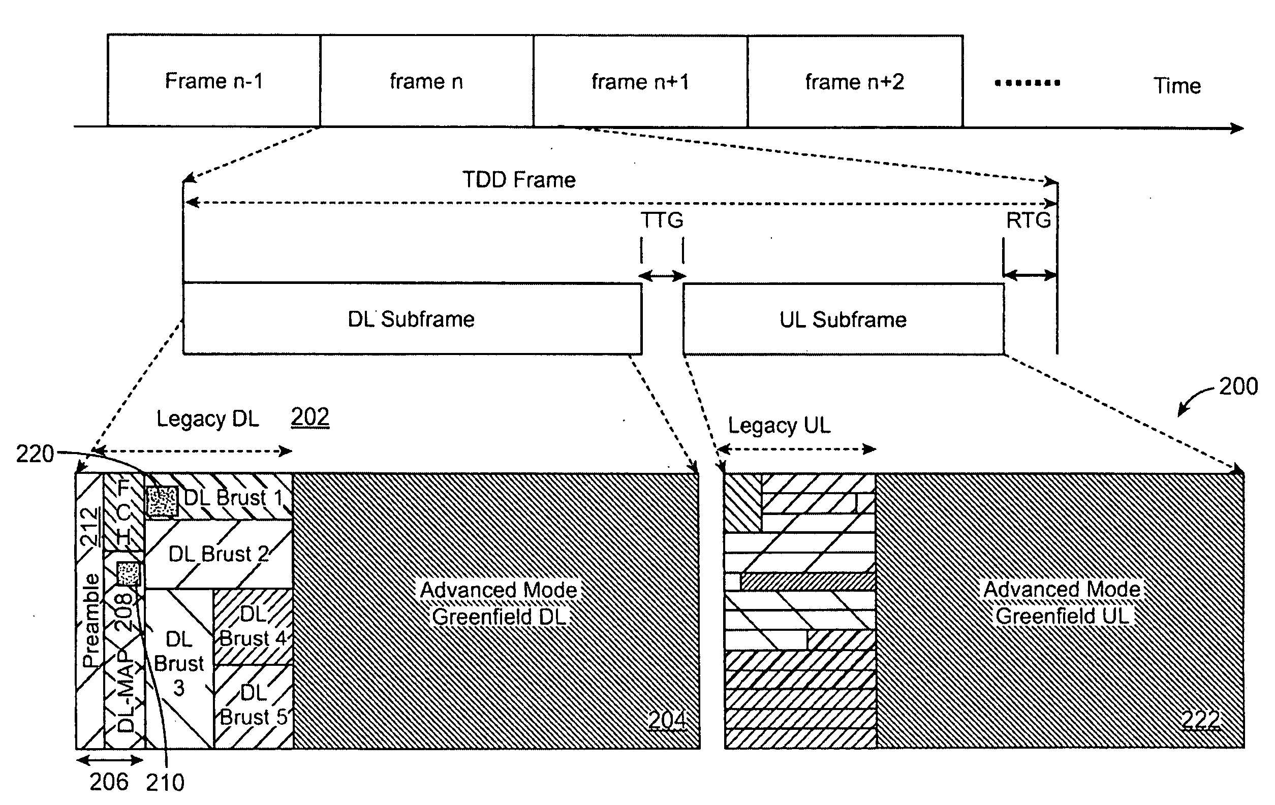
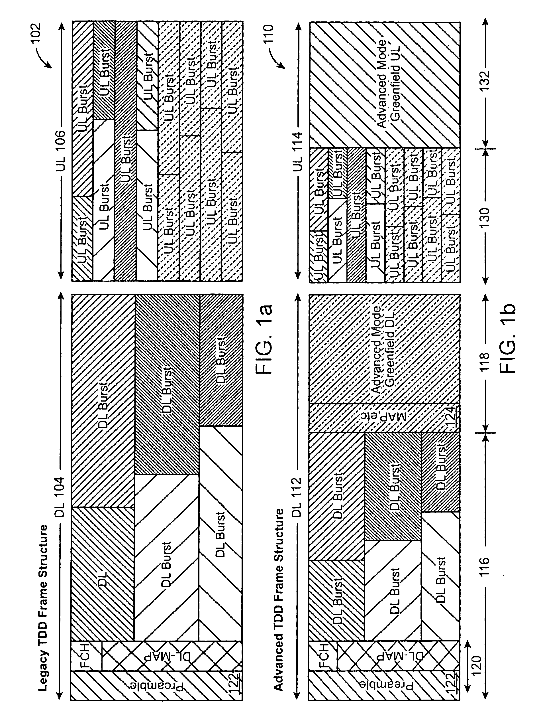
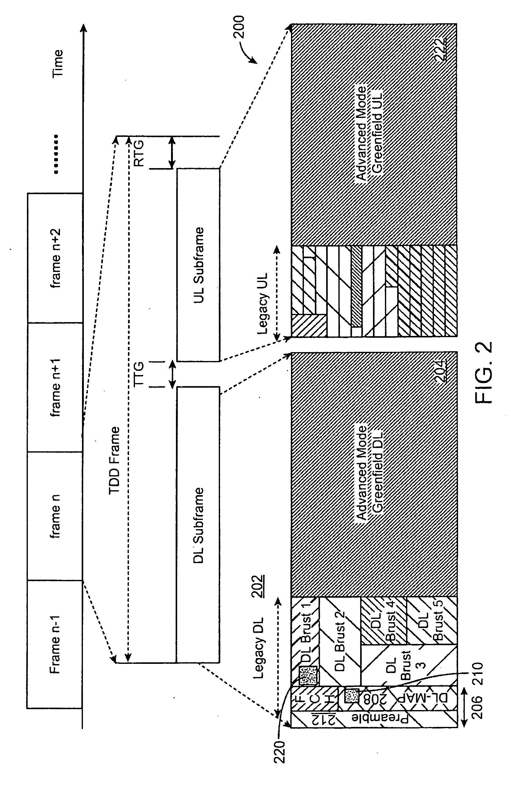
[0036]An advanced technology frame structure with backward compatibility, methods for implementing the advanced technology frame structure, and apparatus for implementing and communicating using the advanced technology frame structure are described herein. The advanced technology frame structure supports legacy communications as well as advanced technology communications by time division multiplexing a legacy frame structure such that minimal or reasonable changes are required for supporting both communications.

[0037]The frame structure and apparatus described herein use improvements to legacy IEEE 802.16e Orthogonal Frequency Division Multiple Access (OFDMA) time division duplex (TDD) frame structure as an example. However, the method and embodiments described herein are not generally limited to application in an OFDMA system, nor are they limited to application in a TDD system. In the timing diagrams, the frame structure includes a time dimension and a frequency dimension. The tim...


PUM


Abstract

An advanced technology frame structure is described herein. The advanced technology frame structure can enhance a first technology frame structure in dimensions of time, frequency, or a combination of time and frequency. A second technology frame structure time division multiplexes second technology subframes with the first technology downlink and uplink subframes. The first technology downlink subframe can be divided into a first technology downlink subframe and one or more second technology downlink subframes. Similarly, the first technology uplink subframe can be divided into a first uplink subframe and one or more second technology uplink subframes. These principles can be expanded upon and can be applied in many communication systems.

Description

CROSS-REFERENCES TO RELATED APPLICATIONS[0001]The application claims the benefit of U.S. Provisional Patent Application No. 60 / 986,257 filed Nov. 7, 2007 for “802.16m FRAME STRUCTURE TO ENABLE LEGACY SUPPORT, TECHNOLOGY EVOLUTION, AND REDUCED LATENCY”; and U.S. Provisional Patent Application No. 61 / 030,183 filed Feb. 20, 2008 for “ADVANCED TECHNOLOGY FRAME STRUCTURE WITH BACKWARD COMPATIBILITY”; which are all incorporated herein by reference in their entirety for all purposes.BACKGROUND[0002]I. Field of the Invention[0003]The invention relates to the field of wireless communications. More particularly, the invention relates to an advanced technology frame structure.[0004]II. Related Art[0005]It is a constant challenge for communication systems to integrate technological improvements in order to remain competitive with later developed communication systems implementing more advanced technology. The problem is even more apparent in wireless communication systems that have large invest...

Claims


Application Information

Patent Timeline
Patent Type & Authority Applications(United States)
IPC IPC(8): H04W40/00
CPCH04L5/0007H04L5/14H04W72/0453H04W72/04H04W72/0446H04W16/14
Inventor MARKS, ROGERWANG, LEIBOURLAS, YAIRGUMMADI, SRIKANTHSTANWOOD, KENNETHPORAT, RON
Owner MONUMENT BANK OF INTPROP LLC
Why Eureka
Try Eureka