Method for Operating an Open-End Spinning Device

Active Publication Date: 2009-05-14
SAURER SPINNING SOLUTIONS GMBH & CO KG
View PDF8 Cites 2 Cited by
  • Summary
  • Abstract
  • Description
  • Claims
  • Application Information

AI Technical Summary

Benefits of technology

[0009]It is therefore the object of the present invention to provide a method, by

Problems solved by technology

In addition to the after-running of the fiber flow after switching off the drawing in and the delayed start-up after switching on the drawing in, the fiber flow may also react with a delay on increasing the drawing in speed.
This can lead to the thread b

Method used


Image

  • Method for Operating an Open-End Spinning Device
  • Method for Operating an Open-End Spinning Device
  • Method for Operating an Open-End Spinning Device

Examples


Embodiment Construction

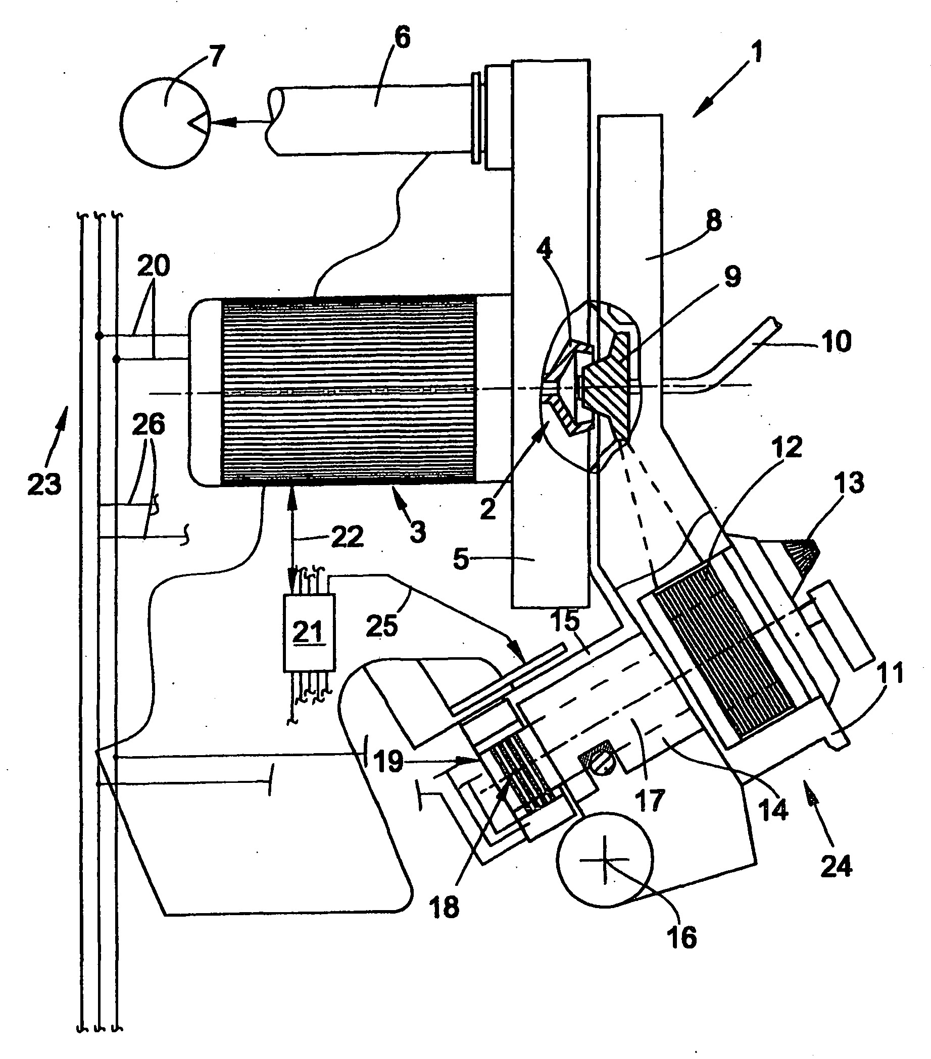
[0020]The view in FIG. 1 shows an open end spinning device 1 of an open end rotor spinning machine, which is arranged in the region of the spinning stations of textile machines of this type. Open end spinning devices 1 of this type are known in principle and described in relative detail, for example, in German Patent Publication DE 196 50 597 A1.

[0021]The open end spinning device 1 comprises a spinning rotor 2 with a rotor cup 4, which revolves during spinning operation at a high speed in a spinning rotor housing 5 which is acted on by a reduced pressure. The rotor housing 5, which is closed at the front by a cover element 8 during spinning operation, is connected for this purpose via a pneumatic line 6 to a reduced pressure source 7, which provides the reduced pressure in the rotor housing 5 necessary for spinning.

[0022]The spinning rotor 2 can be driven in a defined manner by a controllable electric motor single drive 3, which is connected via electric lines 20 to the energy suppl...


PUM

PropertyMeasurementUnit
Fractionaaaaaaaaaa
Fractionaaaaaaaaaa
Speedaaaaaaaaaa

Abstract

The invention relates to a method for operating an open-end spinning device (1), comprising a spinning rotor (2) and an opening roller (12), which can be controlled so as to be driven individually independently of one another, wherein after an interruption in the spinning process takes place as a result of the detection of the absence of a thread, a piecing operation is initiated, comprising a piecing process, in which an upper thread passes through a fiber ring formed in the spinning rotor (2) and is connected to the latter, and a subsequent drawing-in accumulating process which serves to reduce a thin point in the thread following the piecer, wherein during the piercing operation, the opening roller (12) is temporarily driven at a piecing speed which is higher than the operating speed of the opening roller (12).

Description

CROSS-REFERENCES TO RELATED APPLICATIONS[0001]This application claims the benefit of German patent application DE 10 2005 033 562.4, filed Jul. 19, 2005, herein incorporated by reference.BACKGROUND OF THE INVENTION[0002]The present invention relates to a method for operating an open end spinning device comprising a spinning rotor and an opening roller, which can be driven individually, and controlled independently of one another. More particularly, the invention relates to such a method wherein, after an interruption of the spinning process has taken place as a result of the detection of the absence of a thread, a piecing process is introduced, in which an upper thread passes through a fiber ring formed in the spinning rotor and is connected thereto, as well as a subsequent drawing in accumulation, which is used to reduce a thin point in the thread following the piecing.[0003]With increasing requirements of the yarn production process, higher and higher demands are also being made o...

Claims


Application Information

Patent Timeline
IPC IPC(8): D01H4/50
CPCD01H4/50D01H4/44
Inventor LASSMANN, MANFRED
Owner SAURER SPINNING SOLUTIONS GMBH & CO KG
Why Eureka
Try Eureka