Bubble separator

a bubble separator and separator technology, applied in the direction of liquid degasification, liquid degasification regulation/control, separation process, etc., can solve the problems of oil cooler damage, oil cooler damage, and increase in pressure passing through the gaps in the oil cooler, so as to prevent overcooling of the fluid and prevent damage to the cooling mechanism

Inactive Publication Date: 2009-05-14
TOYOTA BOSHOKU KK
View PDF5 Cites 30 Cited by
  • Summary
  • Abstract
  • Description
  • Claims
  • Application Information

AI Technical Summary

Benefits of technology

[0009]In consideration of the circumstances described above, it is an object of the present invention to provide a bubble separator that can prevent damage to a cooling mechanism that is connected downstream of the separator and can prevent overcooling of the fluid.

Problems solved by technology

However, in the proposed technology described above, an oil cooler is simply connected downstream of the bubble separator, and thus, for example, during the start-up of the internal combustion engine, when the oil has a low temperature and a high viscosity, a loss of pressure that passes through the gaps in the oil cooler increases, and there is a concern that the oil cooler will be damaged.
Thus, time is consumed until the oil reaches a suitable temperature range.

Method used


Image

  • Bubble separator
  • Bubble separator
  • Bubble separator

Examples


embodiments

[0073]Below, the present invention will be explained in detail by first through fourth embodiments with reference to the figures. Note that in the first through fourth embodiments, the “bubble separator” according to the present invention is illustrated by a bubble separator that removes the air bubbles that are contained in the lubricating oil of an internal combustion engine.

first embodiment

(1) Structure of the Bubble Separator

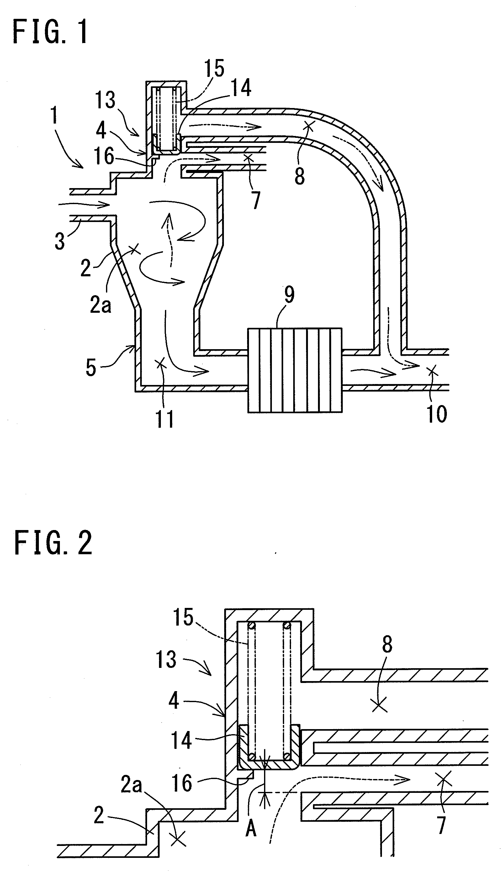
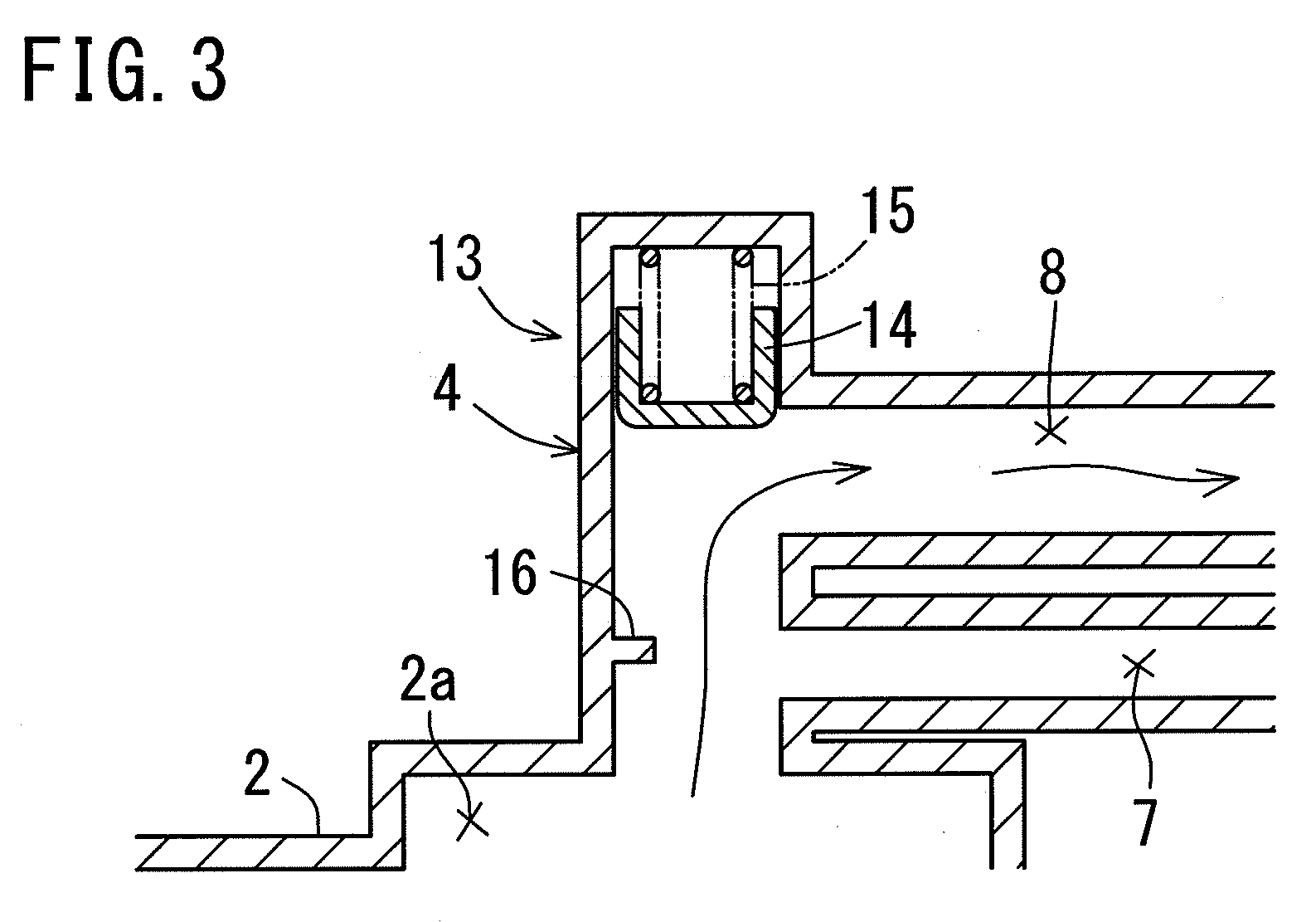
[0074]As shown in FIG. 1, a bubble separator 1 according to the first embodiment is provided with a main body 2 that has a substantially conical separation chamber 2a inside thereof. At the upper portion of the peripheral wall of this main body 2, an oil introduction portion 3 is provided that introduces the oil that contains air bubbles to the inside of the main body 2 in a tangential direction. In addition, at the center portion of the upper end wall of the main body 2, a gas discharge portion 4 is provided for discharging the gas that has been separated in the main body 2 to the outside. Furthermore, at the lower portion of the main body 2, a fluid discharge portion 5 is provided that discharges the oil that has been separated inside the main body to the outside

[0075]A gas discharge passage 7 that has one end thereof connected to the inside of the main body 2 is provided in the gas discharge portion 4. The other end of the gas discharge passag...

second embodiment

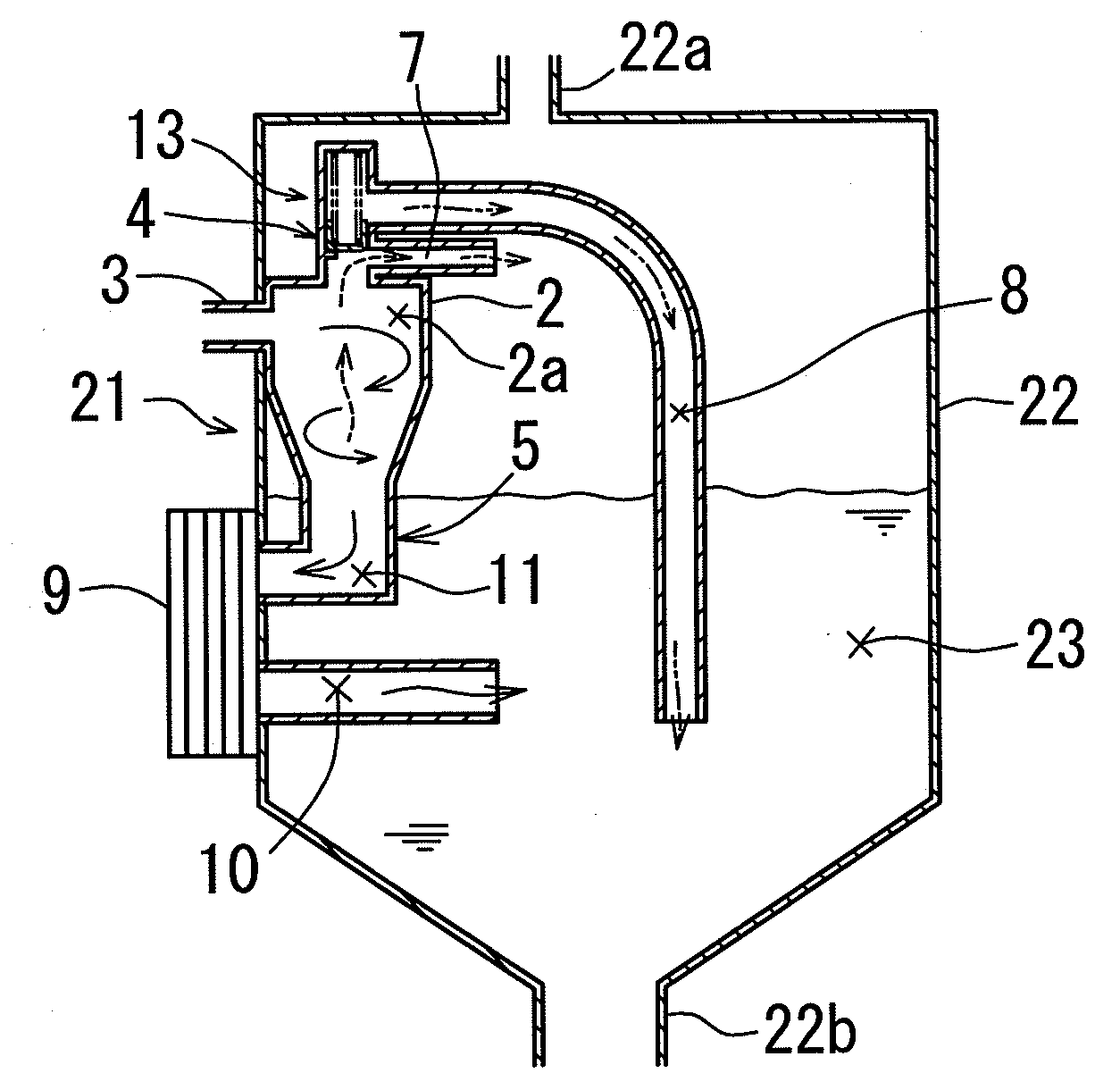
[0087]Next, a bubble separator according to a second embodiment will be explained. Note that in the bubble separator according to the second embodiment, identical reference numerals are appended to structural parts that are substantially identical to those of the bubble separator of the first embodiment, and the explanations thereof are omitted.

[0088]As shown in FIG. 4, a bubble separator 21 according to the second embodiment is disposed inside an oil tank 22. This bubble separator 21 is provided with the main body 2, the oil introduction portion 3, the gas discharge portion 4, and the fluid discharge portion 5. A gas discharge outlet 22a that is provided at the upper portion of the oil tank 22 is connected to a blow-by gas passage (not illustrated). In addition, the oil discharge outlet 22b that is provided at the lower portion of the oil tank 22 is connected to a lubricating path for an internal combustion engine (not illustrated). In addition, the well-known oil cooler 9 is provi...


PUM

PropertyMeasurementUnit
diameteraaaaaaaaaa
pressureaaaaaaaaaa
interior pressureaaaaaaaaaa

Abstract

A bubble separator is a cyclone-type bubble separator having a cooling mechanism (oil cooler) connected downstream thereof, and is provided with a relief mechanism that operates when the interior pressure in a main body increases. The fluid inside the main body escapes downstream of the cooling mechanism due to the operation of the cooling mechanism. In particular, preferably the relief mechanism is provided in a gas discharge portion that is connected to the main body.

Description

INCORPORATION BY REFERENCE[0001]The disclosure of Japanese Patent Application No. 2007-293663 filed on Nov. 12, 2007, including the specification, drawings and abstract is incorporated herein by reference in its entirety.BACKGROUND OF THE INVENTION[0002]1. Field of the Invention[0003]The present invention relates to bubble separators, and in particular, relates to bubble separators that can prevent damage to a cooling mechanism that is connected downstream of the separator and can prevent over-cooling of a fluid.[0004]2. Description of the Related Art[0005]Conventionally, cyclone-type bubble separators are known that remove air bubbles contained in a gas-liquid mixed fluid that is introduced into a main body (refer, for example, to Patent Document 1). In addition, such bubble separators are also generally used to remove the air bubbles in lubricating oil in an internal combustion engine.[0006]Here, the oil that is discharged from a lubricating path in an internal combustion engine n...

Claims


Application Information

Patent Timeline
Patent Type & Authority Applications(United States)
IPC IPC(8): B01D19/00
CPCB01D19/0063B01D19/0057
Inventor SAITO, YASUHIRO
Owner TOYOTA BOSHOKU KK
Why Eureka
Try Eureka