Nacelle Flow Assembly

a technology of nacelle and assembly, which is applied in the direction of air flow influencer, combustion air/fuel air treatment, bends, etc., can solve the problem of reducing the efficiency of the turbofan engine during the cruise conditions of the aircra

Inactive Publication Date: 2009-05-14
RAYTHEON TECH CORP
View PDF71 Cites 24 Cited by
  • Summary
  • Abstract
  • Description
  • Claims
  • Application Information

AI Technical Summary

Problems solved by technology

Disadvantageously, the “thick” inlet lip section may reduce the efficiency of the turbo fan engine duri

Method used


Image

  • Nacelle Flow Assembly
  • Nacelle Flow Assembly
  • Nacelle Flow Assembly

Examples


Embodiment Construction

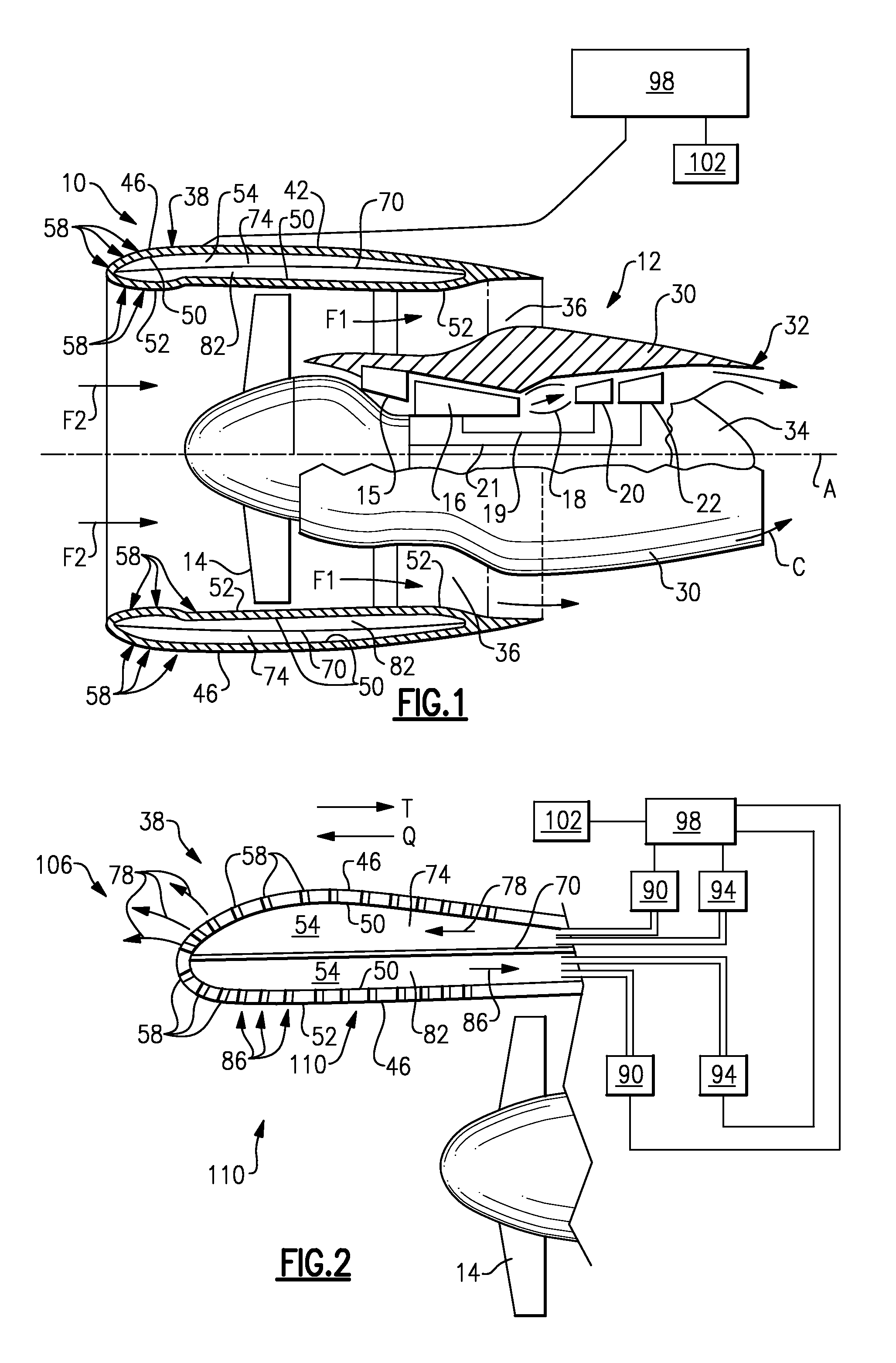
[0012]FIG. 1 illustrates a gas turbine engine assembly 10, which includes “in serial flow communication” fan section 14, low pressure compressor 15, high pressure compressor 16, combustor 18, high pressure turbine 20, and low pressure turbine 22. During operation, air is pressurized in the compressors 15, 16 and mixed with fuel in the combustor 18 to generate hot combustion gases. The hot combustion gases flow through high and low pressure turbines 20, 22, which extract energy from the hot combustion gases. The high pressure turbine 20 powers high pressure compressor 16 through high speed shaft 19 while a low pressure turbine 22 powers fan section 14 and low pressure compressor 15 through low speed shaft 21. The invention is not limited to two spool axial gas turbine architecture described and may be used with other architectures, such as a single spool axial design and a three spool axial design.

[0013]As shown in FIG. 1, gas turbine engine assembly 10 is in the form of a high bypas...


PUM


Abstract

A nacelle assembly for a turbine engine has a cowl for a turbine engine. The cowl has a first surface spaced from a second surface. The second surface defines defining a bypass flow passage. A flow volume is spaced between the first surface and the second surface. A plurality of holes are disposed on the cowl. Each of the plurality of holes are configured to alter local air pressure about one of the first surface and the second surface of the cowl. The plurality of holes are in communication with the flow volume.

Description

BACKGROUND OF THE INVENTION[0001]This invention relates to a nacelle assembly for a gas turbine engine, particularly for an aircraft.[0002]For a gas turbine engine, such as a turbo fan engine, air is pressurized in a compressor and mixed with fuel in a combustor to generate hot combustion gases. These gases flow downstream through the turbine stages of the engine, which extract energy from the gases. In a two spool gas turbine engine, a high pressure turbine powers a high pressure compressor, while a low pressure turbine powers the fan section disposed upstream of the compressor and a low pressure compressor.[0003]Combustion gases are discharged from the turbo fan engine through a core exhaust nozzle while fan air is discharged through an annular fan exhaust nozzle defined at least partially by a nacelle surrounding the core engine. A majority of the propulsion thrust is provided by the pressurized fan air, which is discharged through the fan exhaust nozzle. The remaining thrust is ...

Claims


Application Information

Patent Timeline
IPC IPC(8): B64C21/02B64D29/00F01D25/24F02C7/04
CPCB64D29/00B64D2033/0286B64D2033/0226B64D33/02Y10T137/2842
Inventor JAIN, ASHOK K.
Owner RAYTHEON TECH CORP
Why Eureka
Try Eureka