
Image forming device

a technology of forming device and sheet, which is applied in the direction of electrographic process, instruments, transportation and packaging, etc., can solve the problems of sheet not being able to be smoothly opened and closed, and the cover cannot be smoothly discharged, so as to achieve smooth discharge of sh

Active Publication Date: 2009-05-14
BROTHER KOGYO KK
View PDF14 Cites 13 Cited by
  • Summary
  • Abstract
  • Description
  • Claims
  • Application Information

AI Technical Summary

Benefits of technology

[0008]Aspects of the present invention are advantageous to provide one or more improved image forming devices that make it possible to smoothly discharge a sheet.
[0010]In some aspects of the present invention, the downstream-side end of the catch tray and the upstream-side end of the cover, which face each other, at least partially overlap when viewed in the second direction perpendicular to the first direction and a vertical direction. Therefore, than a known image forming device in which a gap between a catch tray and a cover is formed linearly along the second direction, it is so harder for a leading end of a sheet discharged to enter into the gap between the catch tray and the cover that the sheet can be discharged more smoothly.

Problems solved by technology

Therefore, the front end of the curled sheet is likely to enter into the linearly formed gap, and it might cause a trouble that the sheet cannot smoothly be discharged, such as a paper jam.
However, these ways result in that the cover cannot smoothly be opened and closed.

Method used


Image

  • Image forming device
  • Image forming device
  • Image forming device

Examples


Embodiment Construction

[0023]It is noted that various connections are set forth between elements in the following description. It is noted that these connections in general and, unless specified otherwise, may be direct or indirect and that this specification is not intended to be limiting in this respect.

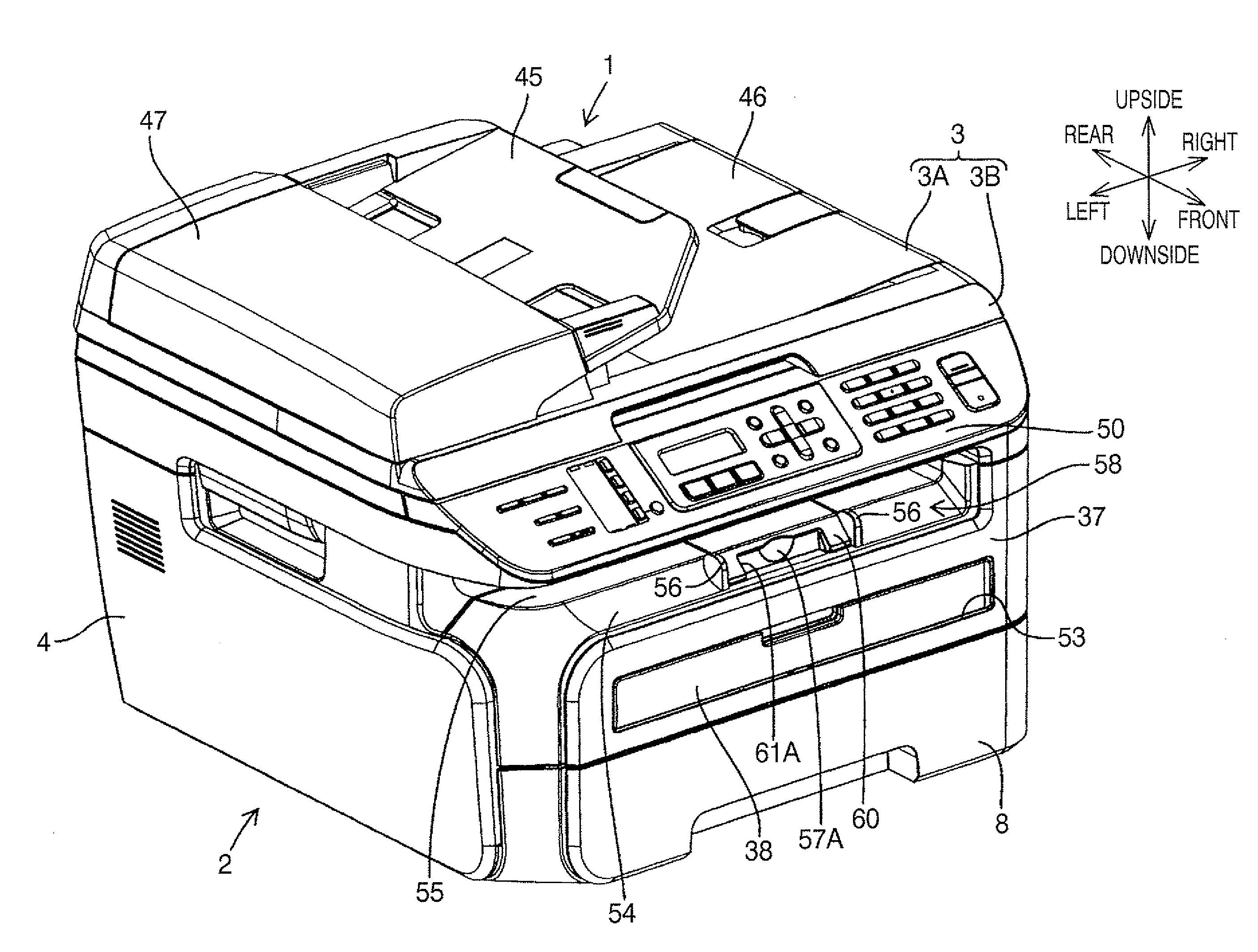
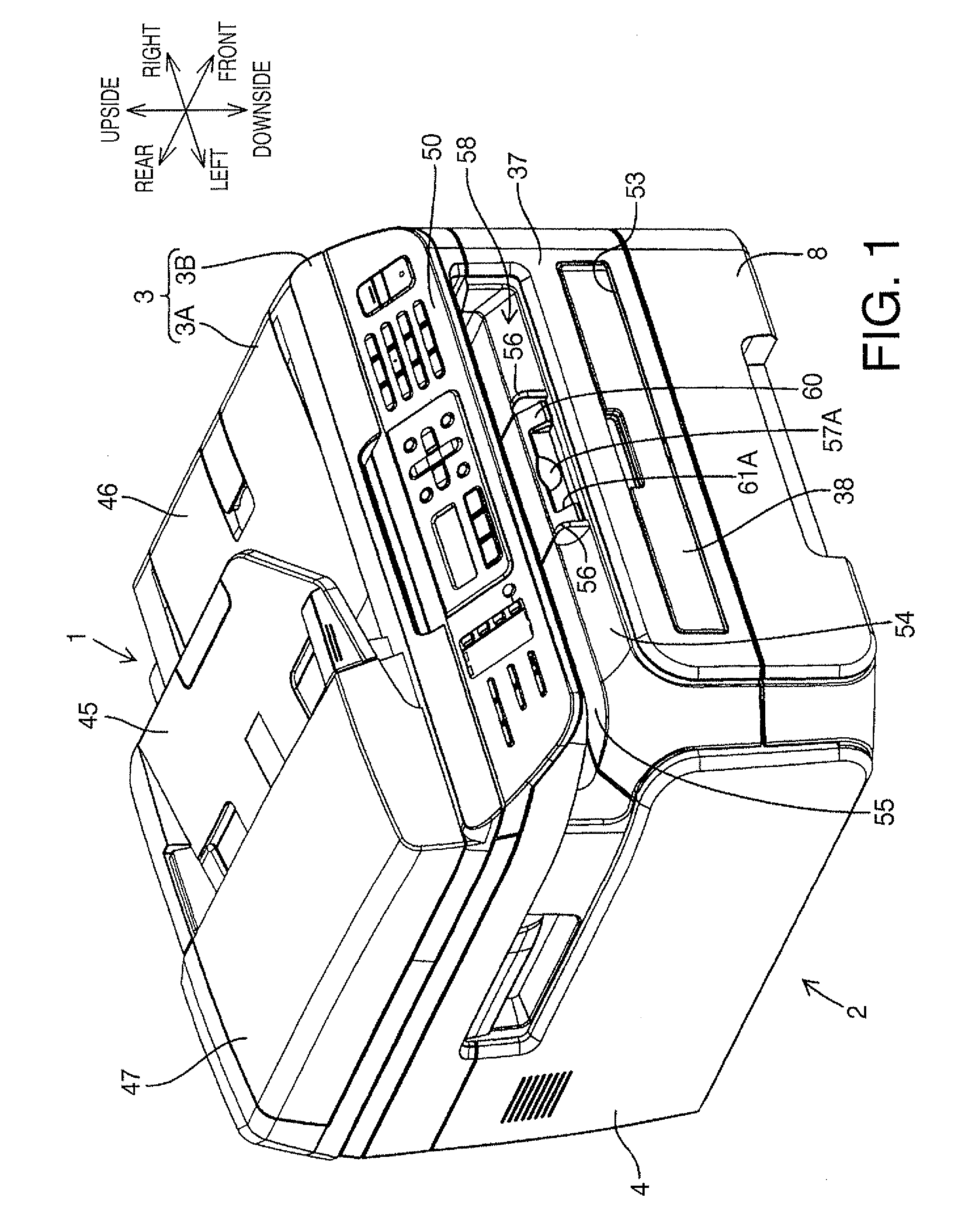
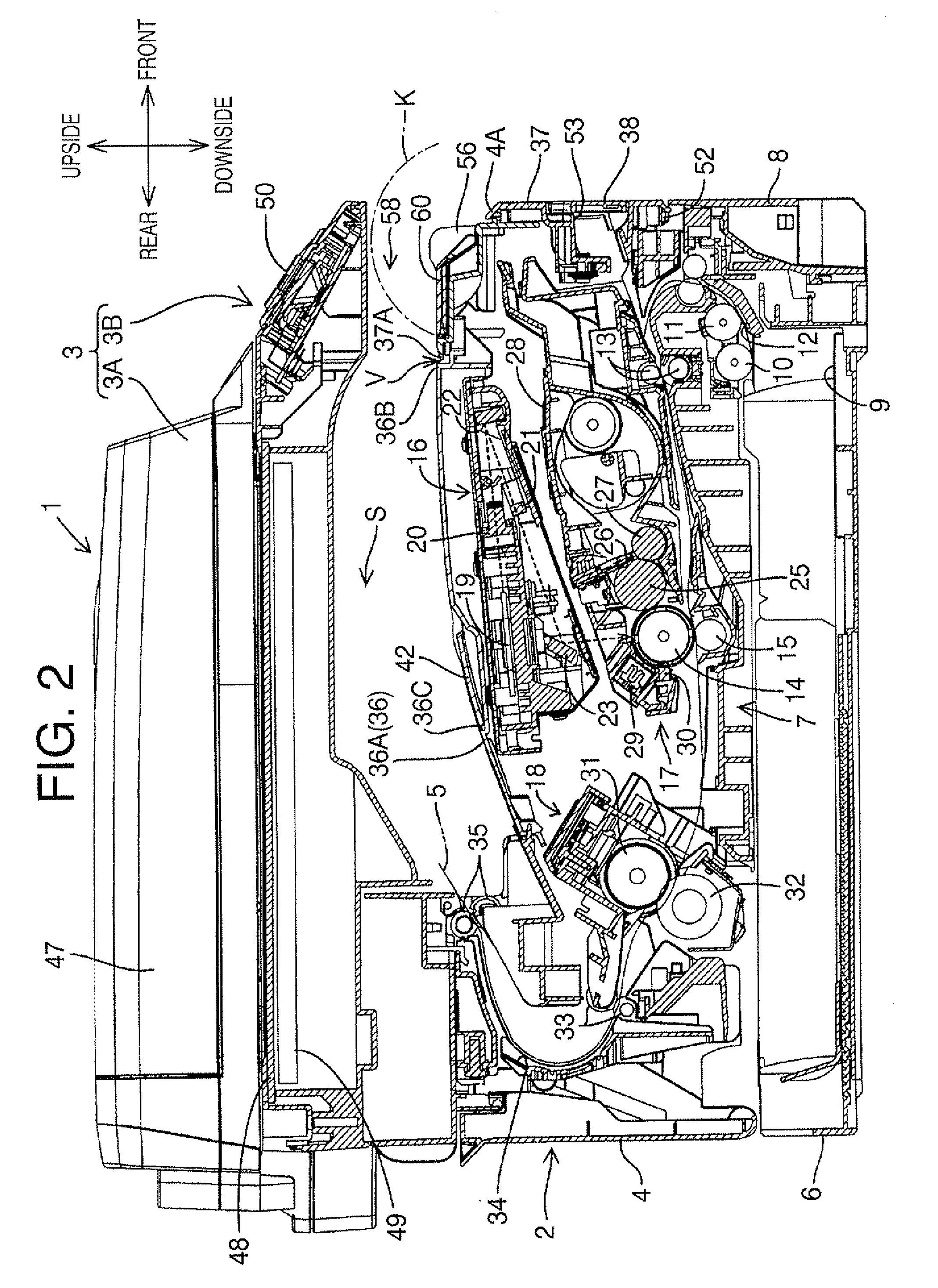
[0024]Hereinafter, an embodiment according to aspects of the present invention will be described with reference to the accompany drawings. Firstly, referring to FIGS. 1 and 2, an overall configuration of an image forming device 1 in an embodiment will be described. FIG. 1 is a perspective view schematically showing an external view of the image forming device 1. FIG. 2 is a cross-sectional side view showing a major portion of the image forming device 1. In the following description, a right side and a left side in FIG. 2 will be defined as a front side and a rear side of the image forming device 1, respectively.

[0025]The image forming device 1 in the present embodiment is a multifunction peripheral provi...


PUM

PropertyMeasurementUnit
Distanceaaaaaaaaaa

Abstract

An image forming device, which is configured to form an image on a sheet, includes a main body casing, a catch tray provided on the main body casing to be loaded with the sheet discharged in a first direction with the image formed thereon, and a cover configured to cover a downstream-side face of the main body casing in the first direction in an openable and closable manner. The catch tray is disposed such that a downstream-side end thereof in the first direction faces an upstream-side end of the cover in the first direction. The downstream-side end of the catch tray and the upstream-side end of the cover are configured to mutually overlap when viewed in a second direction perpendicular to the first direction and a vertical direction.

Description

CROSS-REFERENCE TO RELATED APPLICATION[0001]This application claims priority under 35 U.S.C. §119 from Japanese Patent Application No. 2007-291002 filed on Nov. 8, 2007. The entire subject matter of the application is incorporated herein by reference.BACKGROUND[0002]1. Technical Field[0003]The following description relates to one or more image forming devices such as printers, copy machines, and fax machines.[0004]2. Related Art[0005]An image forming device such as a printer has been known, which includes a catch tray provided on a main body casing thereof to be loaded with a discharged sheet with an image formed thereon, and a cover attached at a downstream-side end of the main body casing in a sheet discharging direction in an openable and closable manner (see Japanese Patent Provisional Publication No. 2006-36437).[0006]In the meantime, a sheet is conveyed while being curled by a plurality of rollers inside the main body casing, and therefore may be discharged in a state curled w...

Claims


Application Information

Patent Timeline
IPC IPC(8): B65H29/00
CPCB65H31/02B65H31/20B65H2301/51256G03G15/6552B65H2405/111646B65H2801/06B65H2405/11161
Inventor ITO, SAKAE
Owner BROTHER KOGYO KK
Learn More