Apparatus for transforming inverse piezoelectric effect into rotary motion and method of manufacturing aforementioned apparatus

a piezoelectric effect and inverse piezoelectric technology, applied in the manufacture/assembly of piezoelectric/electrostrictive devices, transducer types, electrical apparatus, etc., can solve the problems of pusher blade oscillation, electric discharge, pusher blade compression, etc., to eliminate imperfections and inconsistencies, eliminate the effect of inconvenient and simple manufacturing and manufacturing

Inactive Publication Date: 2009-05-14
MULTIMETRIXS
View PDF5 Cites 21 Cited by
  • Summary
  • Abstract
  • Description
  • Claims
  • Application Information

AI Technical Summary

Benefits of technology

[0010]It is a further object to provide a device that ensures that each pusher blade is uniformly secured to the ring with the same orientation, ensuring even and efficient transmission of energy through each pusher blade.
[0011]It is still another object to provide a simple and reliable method of manufacturing and assembling an apparatus for conversion of linear piezoelectric oscillations into a continuous rotary motion.
[0012]It is a further object to provide a method of manufacturing and assembly of a pusher-blade elastic band of the aforementioned apparatus that will eliminate imperfections and inconsistencies in the pusher blades of the elastic band, resulting in loss of energy caused by differences in functional angles, configurations, shapes, and sizes of the pusher blades.
[0013]The invention provides an apparatus for transforming inverse piezoelectric effect into rotary motion. The apparatus contains a stator assembly, a rotor assembly, and an elastic band with pusher blades between the rotor and stator assemblies. More specifically, the stator assembly of the apparatus enables cooperative engagement with a ring of a rotor of a rotary motor. The stator assembly includes a collet, a piezoelectric member, and the aforementioned elastic band. The inner hub-shaped collet has a flexible flange disposed in an axial direction. The piezoelectric element is also cylindrical, the inner surface of the piezoelectric element being in direct engagement with the collet and the outer surface of the piezoelectric element being in direct engagement with the elastic band. An elastic band is formed with pusher blades punched therefrom, the pusher blades all being integral therewith and all made at the same angle. The pusher blades are bent outwardly in the same direction and away from the band. A Teflon coating is then applied to the pusher blades to improve resistance to wear.
[0014]The elastic band includes a pair of torsion spirals disposed on each respective end thereof. The torsion spirals securely retain the elastic band about the piezoelectric element. The pair of torsion spirals disposed at one end of the band is curled upwardly, and the torsion spirals at the other end of the strip are both curled downwardly. The elongated strip is formed into a ring by locking the torsion spirals together. This construction strengthens each blade while eliminating the need for solder, brazing, or any similar operations to form the ring from the strip.
[0015]The device of the invention enables a ring of the rotor to be force-fit over the pusher blades in spring movement with the pusher blades. Thus, outward expansion of the ring causes the pusher blades to engage the ring, always biasing the ring in the direction tangential to the circumference of the ring of the rotor and thus turning the rotor.

Problems solved by technology

The pusher blades are plated such that pressure applied to the pusher blades results in an electric discharge.
Conversely, electrical charge applied to the pusher blades causes the pusher blades to oscillate.
Accordingly, expansion of the inner ring resulting from the piezoelectric effect of the inner ring being coated results in compression of the pusher blades, and this also causes movement of the inner ring relative to the outer ring.
These configurations are problematic.
Inward expansion is prevented since the ring expands outwardly, resulting in loss of efficiency in potential movement and work capacity.
Electricity pulsed at speeds at or exceeding 60,000 pulses per second results in considerable wear on the inside ring and eventually results in separation of the inner plating from the inside ring.
Microscopic deformations occur on the ring which eventually cause ring breakage.
A different effect of ceramic plating on each pusher blade is characterized by uneven wear and loss of power.

Method used


Image

  • Apparatus for transforming inverse piezoelectric effect into rotary motion and method of manufacturing aforementioned apparatus
  • Apparatus for transforming inverse piezoelectric effect into rotary motion and method of manufacturing aforementioned apparatus
  • Apparatus for transforming inverse piezoelectric effect into rotary motion and method of manufacturing aforementioned apparatus

Examples


Embodiment Construction

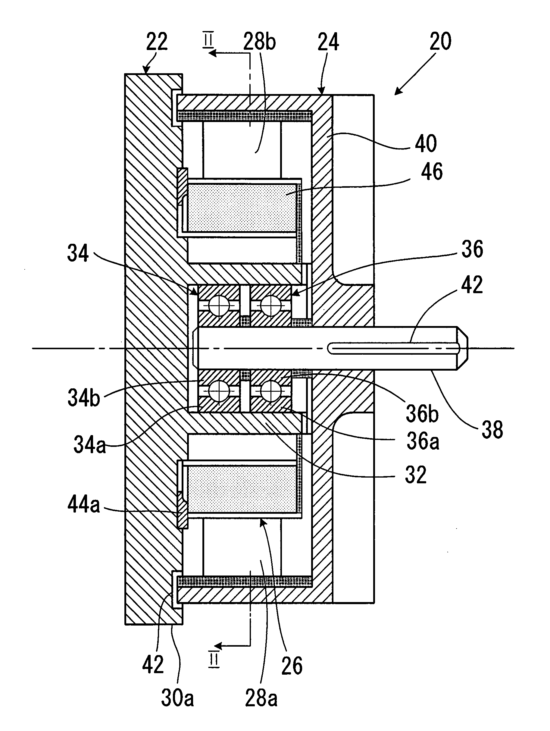
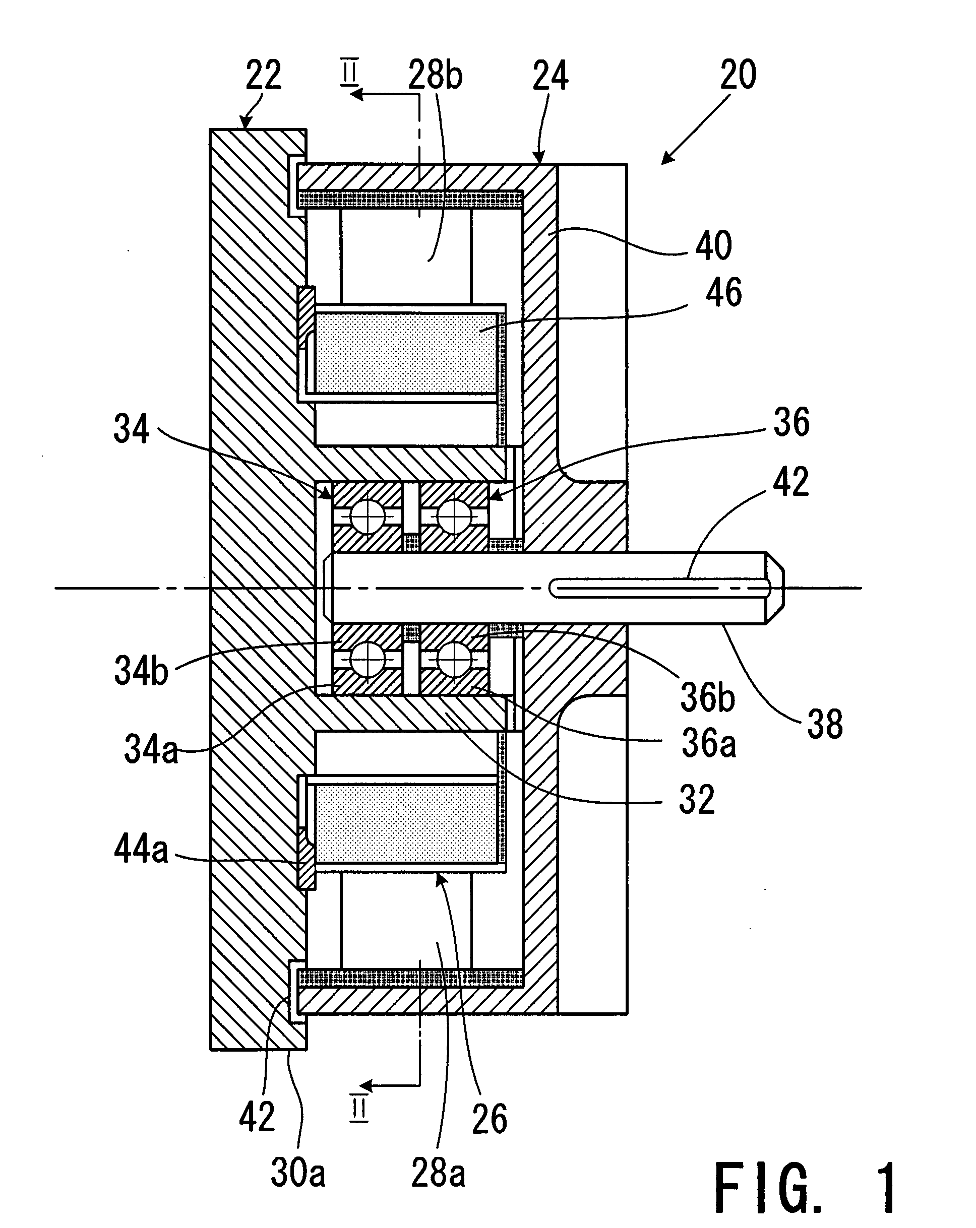
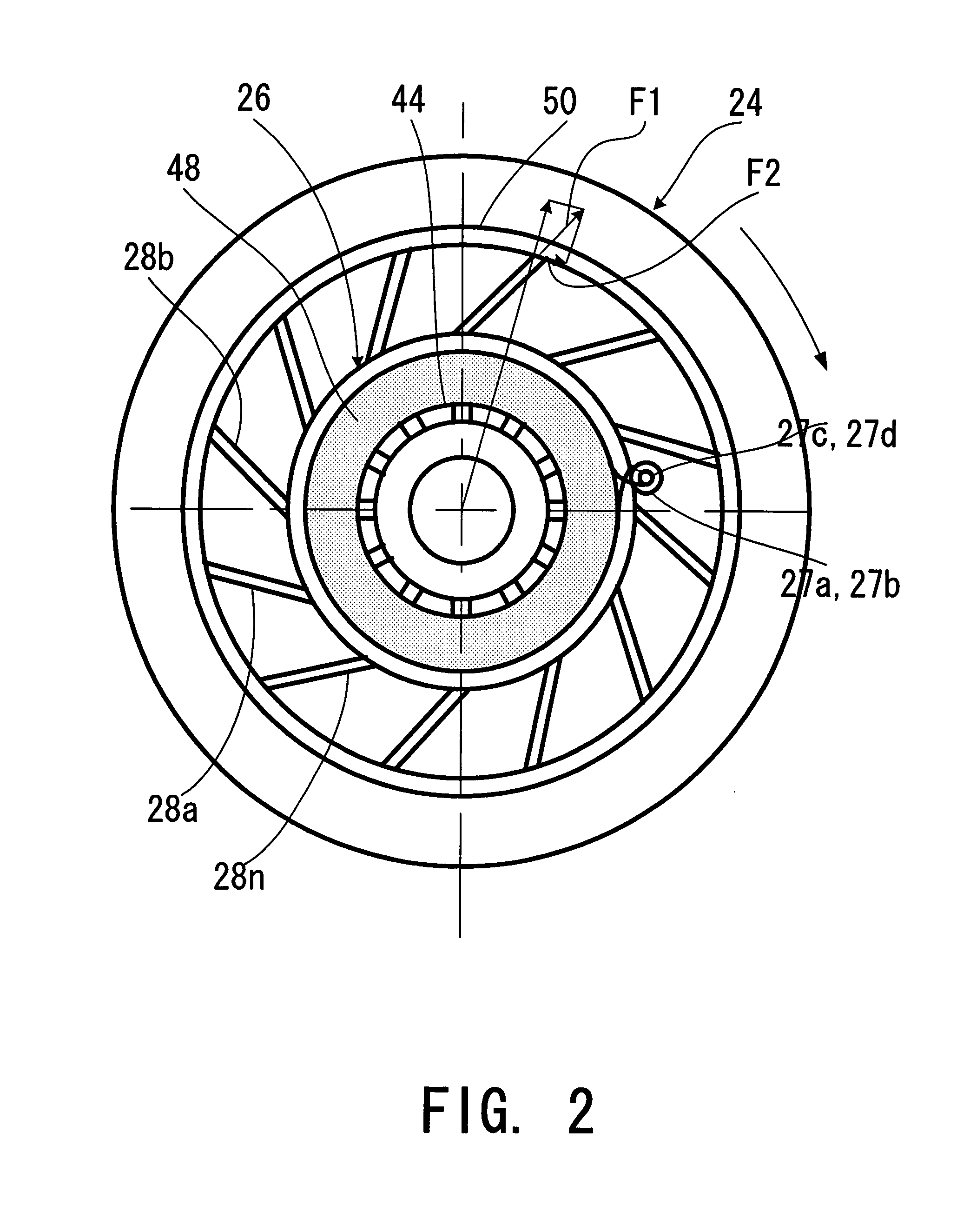
[0025]The apparatus of the invention will be illustrated in the form of a rotary motor. The rotary motor of the invention in which an inverse piezoelectric effect is transformed into a rotary motion is shown in FIGS. 1 and 2, where FIG. 1 is an axial sectional view of the motor and FIG. 2 is a cross-sectional view of the motor along line II-II of FIG. 1. It can be seen that the motor, which as a whole is designated by reference numeral 20, contains a stator assembly 22, a rotor assembly 24, and an elastic band 26 with a plurality of radial pusher blades 28a, 28b, . . . 28n (FIG. 2).

[0026]The stator assembly 22 consists of a flanged member 30 with a central hollow cylindrical hub 32 that houses a bearing assembly which consists of two radial ball bearings 34 and 36. The outer rings 34a and 34b of these bearings are press-fitted into the interior of the hub 32, while the inner rings 36a and 36b of the bearings 34 and 36 are press-fitted onto a rotary shaft 38 of the rotor assembly 24....


PUM

PropertyMeasurementUnit
diameteraaaaaaaaaa
diameteraaaaaaaaaa
widthaaaaaaaaaa

Abstract

An electric motor operating on the principle of conversion of inverse piezoelectric oscillations into continuous rotation. The motor has a stator having a flange that on a bearing rotatingly supports a shaft with a cup-shaped stator attached to the shaft. The flange also supports a ring-shaped piezoelectric element, the outer surface of which is embraced with an elastic band having radial outward blades. The blades abut the inner surface of the rotor and are inclined at an angle that in the point of contact between the tips of the blades and the rotor provides development of a force component in the direction of the rotation of the rotor. The ring-shaped piezoelectric element is fitted onto a collet that compensates for contractions and expansions of the piezoelectric element under the inverse piezoelectric effect.

Description

FIELD OF THE INVENTION[0001]The present invention relates to apparatuses for transforming linear motion into rotary motion, in particular to an apparatus of the aforementioned type having a stator assembly for frictional engagement with a ring of a rotor of a rotary motor, and, more specifically, to the aforementioned apparatus in the form of a stepper motor having a stator assembly and a rotor assembly, which is driven into rotation by a piezoelectric member through a plurality of pusher blades that extend radially outward from the piezoelectric member. The invention also relates to a method of manufacturing the aforementioned device, and, in particular, to the elastic band with pusher blades that transmit motion from the piezoelectric member to the rotor.BACKGROUND OF THE INVENTION[0002]Piezoelectricity is the ability of some materials (notably crystals and certain ceramics) to generate an electric potential in response to applied mechanical stress. The piezoelectric effect is rev...

Claims


Application Information

Patent Timeline
Patent Type & Authority Applications(United States)
IPC IPC(8): H02N2/12H01L41/22
CPCH02N2/002Y10T29/42H02N2/103H02N2/0065
Inventor KESIL, BORIS
Owner MULTIMETRIXS
Why Eureka
Try Eureka