Friction engagement device for work vehicle and work vehicle

a technology for work vehicles and friction engagement devices, which is applied in mechanical actuators, mechanical apparatuses, transportation and packaging, etc., can solve the problems of long time required for engagement, large piston volume, and high cost of hydraulic control

Active Publication Date: 2022-03-22
KOMATSU LTD
View PDF32 Cites 0 Cited by
  • Summary
  • Abstract
  • Description
  • Claims
  • Application Information

AI Technical Summary

Benefits of technology

[0009]An object of the present invention is to easily reduce a time required for engagement in a friction engagement device for a work vehicle while obtaining large urging force suitable for the work vehicle by a return spring.Solution to Problems
[0011]In the friction engagement device according to the present aspect, the first return spring and the second return spring can create an engagement standby state with a small disengaging margin. Thereby: the time required for the engagement can be easily reduced. Further the center axis of the first return spring and the center axis of the second return spring are arranged to coincide with the center axis of the rotating shaft. Therefore, it is possible to secure a space in which the large first return spring and the second return spring can be arranged. Therefore, a large urging force can be obtained by using the large first return spring and the large second return spring.
[0017]The second return spring may be a wave spring. In this case, a large urging force can be obtained by the wave spring arranged concentrically with the rotating shaft. Further, gaps between the first friction plates and the second friction plates can be secured uniformly by the wave spring. Therefore, the cooling efficiency of the friction plates can be improved.
[0019]The friction engagement device may further include a spacer and a restriction member. The spacer may be arranged between the piston and the first return spring. The restricting member may restrict a movement of the spacer toward the release position. With the piston at the release position, the spacer may be separated from the piston. In this case, the standby position can be easily adjusted by setting a distance between the piston and the spacer when the piston is located at the release position depending on the shape of the spacer. Thus, the timing at which the friction plates enters the engagement standby state can be easily adjusted.
[0021]According to the present invention, a time required for engagement in a friction engagement device for a work vehicle can be easily reduced while obtaining large urging force suitable for the work vehicle by a return spring.

Problems solved by technology

Therefore, when the number of friction plates is large, there is a problem that the time required for engagement is long.
A similar problem also occurs when the volume of the piston is large.
However, this requires extremely accurate hydraulic control.
On the other hand, in a work vehicle, the torque passing through the friction engagement device is large.
Therefore, the urging force required for the return spring is large.
However, it is difficult to secure a space for a large return spring around the piston and the friction plates.

Method used


Image

  • Friction engagement device for work vehicle and work vehicle
  • Friction engagement device for work vehicle and work vehicle
  • Friction engagement device for work vehicle and work vehicle

Examples


Embodiment Construction

)

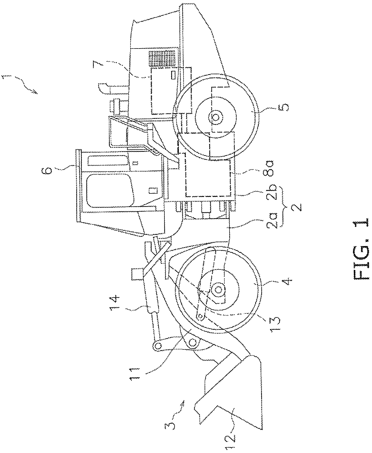
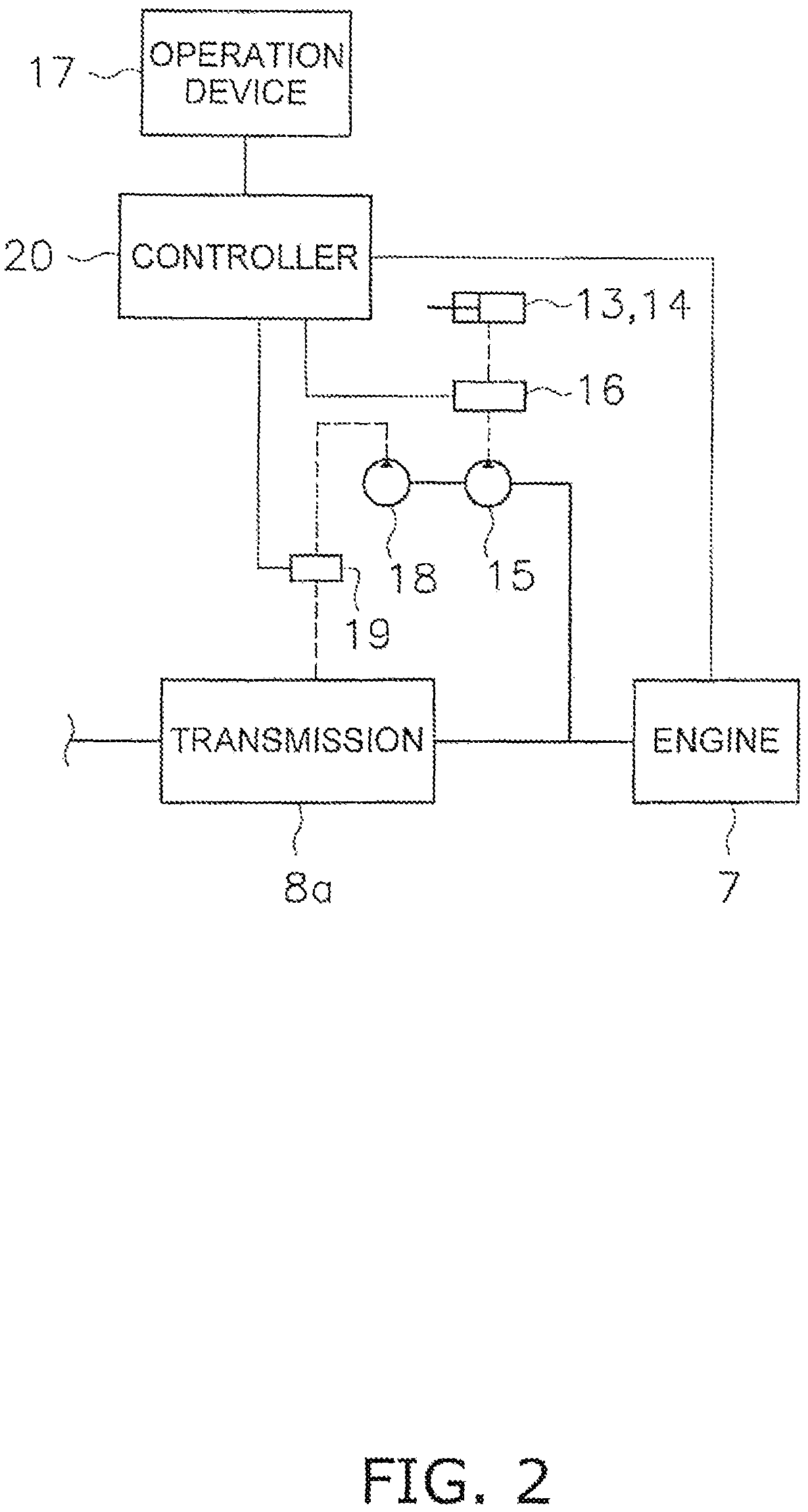
[0027]Hereinafter, embodiments of the present invention will be described with reference to the drawings. FIG. 1 is a side view of a work vehicle 1 according to an embodiment of the present invention. FIG. 2 is a block diagram showing a configuration of a control system of the work vehicle 1. As illustrated in FIG. 1. the work vehicle 1 includes a body frame 2, a work implement 3, traveling wheels 4 and 5, a cab 6, an engine 7, and a transmission 8a.

[0028]The body frame 2 includes a font frame 2a and a rear frame 2b. The front frame 2a is attached to the front of the rear frame 2b. The front frame 2a is rotatably connected to the rear frame 2b. The traveling wheels 4 and 5 include a front wheel 4 and a rear wheel 5. The front wheel 4 is rotatably attached to the front frame 2a. The rear wheel 5 is rotatably attached to the rear frame 2b.

[0029]The work vehicle 1 can perform work such as excavation using the work implement 3. The work implement 3 is driven by hydraulic fluid from a...


PUM


Abstract

A friction engagement device includes a rotating shaft, first friction plates that rotate with the rotating shaft, second friction plates arranged to face the first friction plates, an oil chamber supplied with hydraulic fluid, a piston movably provided between engagement and release positions, and first and second return springs. The piston is pressed toward the engagement position by hydraulic pressure of the oil chamber. The first return spring contacts the piston from the engagement position to a standby position between the release position and the engagement position and urges the piston toward the release position. The second return spring contacts the piston from the engagement position to the release position and urges the piston toward the release position. Center axes of the first and second return springs are arranged to coincide with a center axis of the rotating shaft.

Description

CROSS-REFERENCE TO RELATED APPLICATIONS[0001]This application is a U.S. National stage application of International Application No. PCT / JP2019 / 007559, filed on Feb. 27, 2019. This U.S. National stage application claims priority under 35 U.S.C. 119(a) to Japanese Patent Application No. 2018-062236, filed in Japan on Mar. 28, 2018, the entire contents of which are hereby incorporated herein by reference.BACKGROUNDField of the Invention[0002]The present invention relates to a friction engagement device for a work vehicle and a work vehicle.Background Information[0003]A friction engagement device includes a piston, a plurality of first friction plates, and a plurality of second friction plates. The first friction plates are connected to the rotating member. The second friction plates are connected to a member that restricts the rotation direction. In the friction engagement device, the first friction plates and the second friction plates are engaged each other by pressing a piston towar...

Claims


Application Information

Patent Timeline
Patent Type & Authority Patents(United States)
IPC IPC(8): B60K17/06F16D13/69F16D25/0638F16D25/12
CPCB60K17/06F16D13/69F16D25/0638F16D25/12
Inventor NAITO, SHINICHITANAKA, DAIKIMORIGUCHI, KYOUSUKE
Owner KOMATSU LTD
Why Eureka
Try Eureka