
Press-molded door beam for a vehicle, having a longitudinal groove part protruding at the beam end

a technology of longitudinal grooves and door beams, which is applied in the direction of vehicle components, roofs, and monocoque constructions, can solve the problems of the manufacturing process and the complexity of the door beam, and achieve the effects of improving yield, reducing weight, and simplifying the manufacturing process of the door beam

Inactive Publication Date: 2008-07-15
HONDA MOTOR CO LTD
View PDF5 Cites 4 Cited by
  • Summary
  • Abstract
  • Description
  • Claims
  • Application Information

AI Technical Summary

Benefits of technology

[0007]In light of the above circumstances, an object of the present invention is to provide a door beam structure for simplifying the manufacturing process thereof, improving the yield, and reducing the weight.
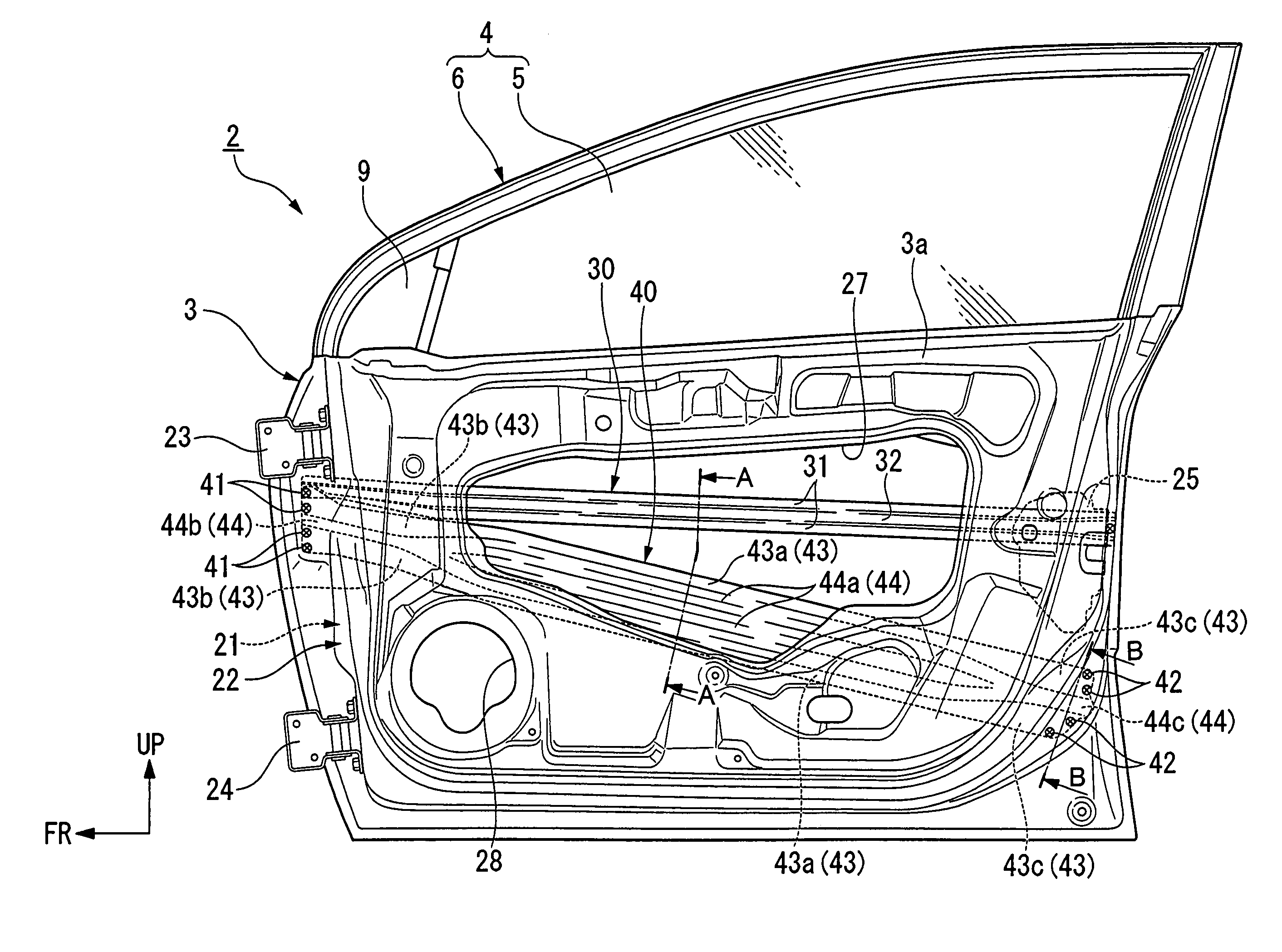
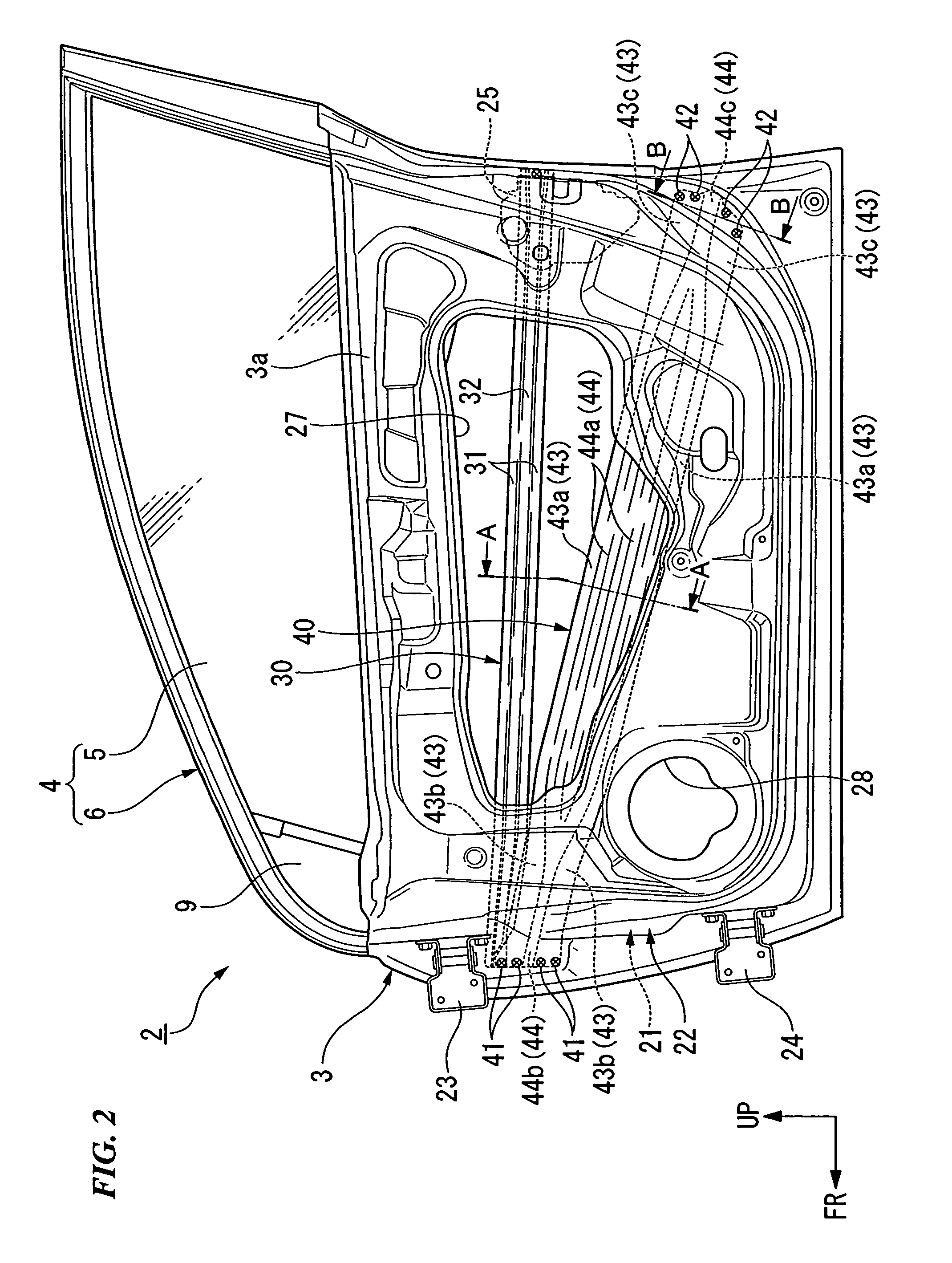
[0012]In accordance with the above structure, only the groove part having high rigidity is protruded from an end of the door beam, thereby increasing the effective lap width between the door beam and the vehicle body by the protruding length of the groove part. Therefore, it is possible to improve the rigidity in the event of an impact against the door while the weight of the door beam can be reduced. In addition, the groove part can protrude from the end of the door beam (i.e., after the press-molding) in accordance with the cut shape of the base member (i.e., before the press-molding), thereby allowing simplification of the manufacturing process of the door beam.
[0013]In the groove part, an end part may have a deeper groove in comparison with a groove in a central part along the extending direction. Such a shallow groove in the central part contributes to space-saving in the central part of the door beam in its extending direction, while such a deep groove in the end part contributes to improving the rigidity in the event of an impact against the door.
[0014]In a preferable example, in the groove part, a plurality of groove lines are formed in a central part along the extending direction, and they are gradually transformed into a single groove in an end part along the extending direction. In this case, a plurality of relatively shallow grooves are formed in the central part in the extending direction of the door beam so as to provide desired rigidity and a space-saving effect. In contrast, at the end part of the door beam, a relatively deep single groove is formed so that relatively wide flat parts can be secured for fastening the door beam to the door main body. Therefore, the rigidity of the door beam can be secured uniformly along its extending direction, and simultaneously, a sufficient width for fastening the door beam to the door main body can be secured without increasing the vertical width of the end part of the door beam. Accordingly, it is possible to increase the yield with respect to the press-molding of the door beam.
[0015]In a typical example, the groove part protrudes outward in the extending direction, from a joint part (e.g., a rear joint part 42 in the embodiment) of the door beam, which is provided for joining said end of the door beam to the main body of the door. Accordingly, the joint part is not formed excessively close to the edge of the door beam. Therefore, the door beam can be stably fastened, and the protruding groove part contributes to improving the rigidity in the event of an impact against the door.

Problems solved by technology

Therefore, a measure for suppressing such a decrease in the rigidity is required, and such a measure may cause complication of the process for manufacturing the door beam.

Method used


Image

  • Press-molded door beam for a vehicle, having a longitudinal groove part protruding at the beam end
  • Press-molded door beam for a vehicle, having a longitudinal groove part protruding at the beam end
  • Press-molded door beam for a vehicle, having a longitudinal groove part protruding at the beam end

Examples


Embodiment Construction

[0024]Hereinafter, an embodiment in accordance with the present invention will be described with reference to the appended figures. In the following explanations, directions such as front, back, right, and left coincide with those of the vehicle if no specific explanation is provided. Additionally, in the figures, arrows indicated by reference symbols FR, LH and UP respectively designate the front side, the left side, and the upper side of the vehicle.

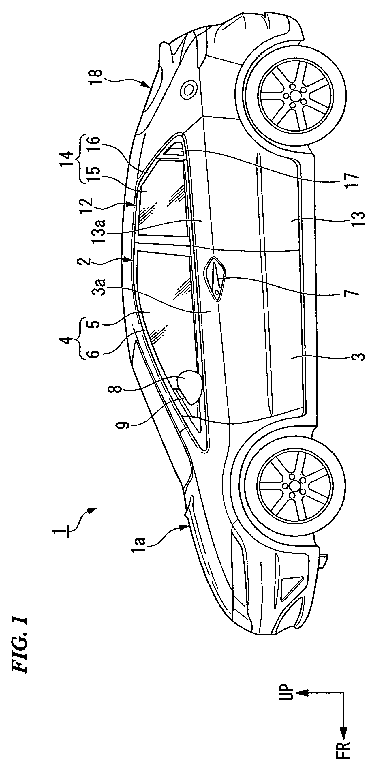
[0025]FIG. 1 is a side view showing a vehicle 1 in the embodiment. The vehicle 1 is a two-box type, and has a vehicle body 1a having a monocoque structure in which panel parts and vehicle-body frame parts are joined integrally to each other. Openings provided on each side of the vehicle are closed and opened using a front door 2 and a rear door 12. The front door 2 consists of a door main body 3 as a lower part of the door and a window part 4 as an upper part of the door, which are formed integrally, and the rear door 12 also consists ...


PUM


Abstract

A structure of a door beam arranged inside a main body of a door in a vehicle. The door beam is press-molded, a recessed groove part is formed in the door beam along its extending direction, and an end of the groove part protrudes outward from an end of the door beam in the extending direction. In the groove part, an end part may have a deeper groove in comparison with a groove in a central part along the extending direction, or a plurality of groove lines may be formed in a central part along the extending direction, and they may be gradually transformed into a single groove in an end part. Preferably, the groove part protrudes outward in the extending direction, from a joint part of the door beam, which is provided for joining said end of the door beam to the main body of the door.

Description

BACKGROUND OF THE INVENTION[0001]1. Field of the Invention[0002]The present invention relates to the structure of a door beam arranged in a main body of a door in a vehicle.[0003]Priority is claimed on Japanese Patent Application No. 2005-374507, filed Dec. 27, 2005, the content of which is incorporated herein by reference.[0004]2. Description of the Related Art[0005]In a known door beam structure, an end of a door beam, made from a steel pipe, is cut diagonally so as to improve the yield and reduce the weight thereof (see Japanese Unexamined Patent Application, First Publication No. H9-226369).[0006]In the above conventional structure, the closer to the head of the door beam, the smaller the rigidity of the beam. Therefore, a measure for suppressing such a decrease in the rigidity is required, and such a measure may cause complication of the process for manufacturing the door beam. In order to solve this problem, the door beam may be made by press-molding so as to improve flexibili...

Claims


Application Information

Patent Timeline
Patent Type & Authority Patents(United States)
IPC IPC(8): B60J7/00
CPCB60J5/0425B60J5/0444B60J5/0437B60J5/0429
Inventor KATOU, MASAHIROKOBAYASHI, FUTOSHI
Owner HONDA MOTOR CO LTD
Learn More