
Medical safety monitor system

a medical safety and monitor technology, applied in the field of alert systems, can solve the problems of inability to quickly notify the proper medical authorities, serious medical conditions may exist without a means of rapid notification, and prior art computer-based systems impose a degree of complexity and inherent cost, and achieve the effect of reducing power requirements

Inactive Publication Date: 2009-05-14
PRIOR RICH
View PDF6 Cites 24 Cited by
  • Summary
  • Abstract
  • Description
  • Claims
  • Application Information

AI Technical Summary

Benefits of technology

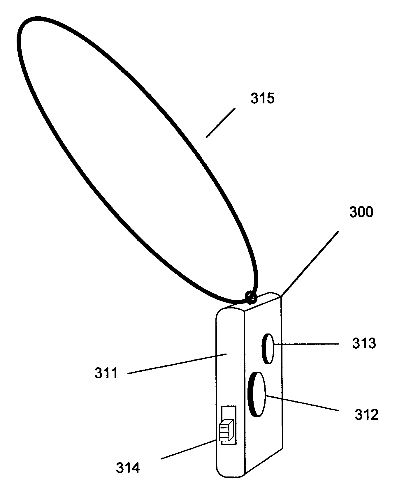
[0025]Further embodiments include a first switch, contained in the housing, operable to cancel transmission of the alert signal when activated and a second switch, contained in the housing, operable to enable the transmitter to transmit the alert signal when activated. In another embodiment, the motion sensor further outputs a large signal indicative that the individual has fallen and potentially needs medical assistance, the circuitry processes the signal to determine the large signal and outputs a third signal in response thereof and the transmitter responsive to the third signal for outputting the alert signal. Other embodiments include means for adjusting a threshold for detection of the absence of signal and means for adjusting the duration of the second period of time. In yet another embodiment, the circuitry includes discrete analog and logic components to minimize the power requirements. In still another embodiment, the transmitter is configured for short-range transmission to a dedicated receiver.
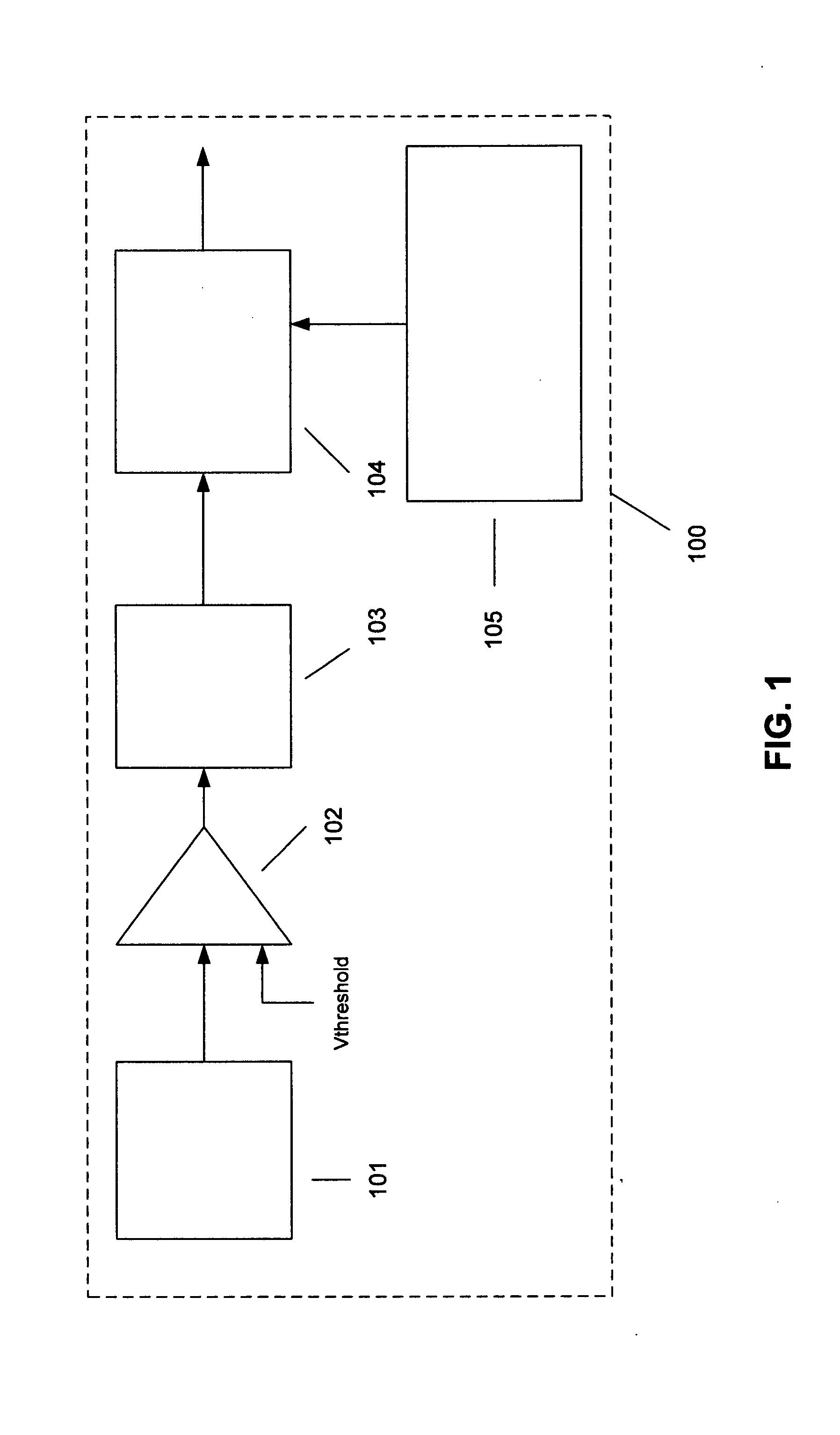
[0027]In another embodiment, a medical alert system is presented that including a remote control unit including a housing for containing the unit wearable by an individual. A motion sensor is contained within the housing. The motion sensor outputs a signal indicative of motion of the individual where an absence of signal indicates a potential need for medical assistance for the individual. A low power circuitry, contained in the housing, processes the signal to determine the absence of signal. The circuitry outputs a first signal after a first period of time when the absence of signal has been detected for a duration of the first period of time, and the circuitry outputs a second signal after a second period of time, the second period of time being substantially longer than the first period of time, when the absence of signal has been detected for a duration of the second period of time. A transmitter, contained in the housing, is responsive to the first and second signal for transmitting an alert signal indicating need for the medical assistance when the first signal and the second signal is output by the circuitry. The alert signal is repeated at intervals of the first period of time and a first switch, contained in the housing, is operable to cancel transmission of the alert signal when activated. An alert signal receiver module includes a receiver configured to receive the transmitted alert signal and an alert module for notifying proper authorities of a medical or situation. Another embodiment includes a second switch, contained in the housing, operable to enable the transmitter to transmit the alert signal when activated. In a further embodiment, the motion sensor further outputs a large signal indicative that the individual has fallen and potentially needs medical assistance. The circuitry processes the signal to determine the large signal and outputs a third signal in response thereof and the transmitter responsive to the third signal outputs the alert signal. Further embodiments include means for adjusting a threshold for detection of the absence of signal and means for adjusting the duration of the second period of time. In yet another embodiment, the circuitry includes discrete analog and logic components to minimize the power requirements.

Problems solved by technology

Unfortunately for some, a catastrophic event may overcome them too quickly to press the alert button.
Conversely, a medical event may overcome at risk individuals too slowly for the individuals to recognize that a serious problem exists; for example, without limitation, they may slowly lapse into a coma, thinking they are just “taking a nap.” In either case, a serious medical condition may exist with no means for rapid notification of the proper medical authorities.
As disclosed, the prior art computer-based system imposes a degree of complexity (and inherent cost) that may not be required for many situations of at risk individuals.
A main limitation of prior art computer-based systems relates to the use of computers in medical alert situations, especially in applications where a computer is incorporated as an integral part of the wearable or attachable unit.
Computers, or micro-controllers as may be applied, consume less-than-negligible power, and often in remote-control applications, their use is limited to intermittent operation in miniature units or continuous operation in larger, often-not-wearable units.
Although various sleep modes of micro-controllers may be incorporated to reduce power, it is normally at the expense of external (to the micro-controller) complexity.
Having the computer located in a fixed-base monitoring station is also problematic.
The large size and weight of a system using a large battery may discourage the use of the system as a wearable device, and the frequent change of batteries, if small batteries are used, may discourage use and increase the risk of a dead battery being left in the device.
Furthermore, additional circuitry to address power issues may add cost and complexity to the system.
Overall, the use of a computer, either in the remote unit or in a fixed base station, entails a host of power supply issues that preclude an efficient, compact, low-cost medical alert system.

Method used


Image

  • Medical safety monitor system
  • Medical safety monitor system
  • Medical safety monitor system

Examples


Embodiment Construction

[0029]The present invention is best understood by reference to the detailed figures and description set forth herein.

[0030]Embodiments of the invention are discussed below with reference to the Figures. However, those skilled in the art will readily appreciate that the detailed description given herein with respect to these figures is for explanatory purposes as the invention extends beyond these limited embodiments. For example, it should be appreciated that those skilled in the art will, in light of the teachings of the present invention, recognize a multiplicity of alternate and suitable approaches, depending upon the needs of the particular application, to implement the functionality of any given detail described herein, beyond the particular implementation choices in the following embodiments described and shown. That is, there are numerous modifications and variations of the invention that are too numerous to be listed but that all fit within the scope of the invention. Also, ...


PUM


Abstract

A medical alert system is presented. The system includes a remote control unit wearable by an individual. A motion sensor outputs a signal indicative of motion of the individual where an absence of signal indicates a potential need for medical assistance. A low power circuitry processes the signal to determine the absence of signal. The circuitry outputs a first signal after a first period of time when the absence of signal has been detected and a second signal after a second period of time when the absence of signal has been detected. A transmitter is responsive to the first and second signal transmits an alert signal indicating need for the medical assistance. The alert signal is repeated at intervals of the first period of time. An alert signal receiver module is configured to receive the transmitted alert signal and notify proper authorities of a medical or situation.

Description

FEDERALLY SPONSORED RESEARCH OR DEVELOPMENT[0001]Not applicable.REFERENCE TO SEQUENCE LISTING, A TABLE, OR A COMPUTER LISTING APPENDIX[0002]Not applicable.COPYRIGHT NOTICE[0003]A portion of the disclosure of this patent document contains material that is subject to copyright protection. The copyright owner has no objection to the facsimile reproduction by anyone of the patent document or patent disclosure as it appears in the Patent and Trademark Office, patent file or records, but otherwise reserves all copyright rights whatsoever.FIELD OF THE INVENTION[0004]The present invention relates generally to alert systems and, more specifically, to a wearable remote control alert activator that is able to monitor lack of movement of a subject and contact a central station upon detecting an emergency situation.BACKGROUND OF THE INVENTION[0005]Many currently known medical alert devices, akin to the “Life Alert” medical response pendant or wristband, enable at risk individuals live with a cer...

Claims


Application Information

Patent Timeline
IPC IPC(8): G08B1/08
CPCG08B21/04
Inventor PRIOR, RICH
Owner PRIOR RICH
Learn More